DA14531MOD SmartBond TINYTM Module Preliminary General Description The DA14531 TINYTM Module, is the first Dialog Bluetooth® Low Energy module based on world’s lowest power DA14531 SoC. The module offers a unique combination of lowest power, integration of all external components including antenna at a very affordable cost. It is designed to enable use of Bluetooth Low Energy in applications where BLE was prohibitive so far because of cost or complexity.
DA14531MOD SmartBond TINYTM Module Preliminary Applications ■ ■ ■ ■ ■ ■ ■ ■ ■ ■ ■ ■ ■ ■ Beacons Remote Controls, Proximity tags Low Power Sensors Commissioning/Provisioning RF pipe Toys Industrial applications Data acquisition Wellness Infotainment IoT Robotics Gaming Datasheet CFR0011-120-00 Revision 2.
DA14531MOD SmartBond TINYTM Module Preliminary Contents General Description ...........................................................................................................................1 Key Features .......................................................................................................................................1 Applications ........................................................................................................................................
DA14531MOD SmartBond TINYTM Module Preliminary Figures Figure 1: SmartBond TINY Module Block Diagram ..............................................................................6 Figure 2: Pinout Diagram Top View ......................................................................................................7 Figure 3: Mechanical Drawing ............................................................................................................13 Figure 4: Module Footprint Top View ...............
DA14531MOD SmartBond TINYTM Module 1 [1] [2] Preliminary References DA14531, Datasheet, Revision 3.0, Dialog Semiconductor. DA14585/DA14531 SW Platform Reference Manual (can be retrieved via web from https://www.dialog-semiconductor.com/products/connectivity/bluetooth-lowenergy/products/da14531) Datasheet CFR0011-120-00 Revision 2.
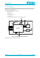
DA14531MOD SmartBond TINYTM Module 2 Preliminary Block Diagram SmartBond TINY™ module is based on the Dialog Semiconductor DA14531 SoC configured in buck mode. With an integrated 1Mbit flash, 32MHz XTAL and a printed antenna, it allows faster time to market at reduced development cost. The module, as seen in Figure 1, comprises of: - 1 Mbit SPI FLASH - 32MHz XTAL - 2 decoupling capacitors - a power inductor - a CLC filter and matching components for the printed antenna. VBAT J7 J12 (RST) 2.
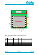
DA14531MOD SmartBond TINYTM Module 3 Preliminary Pinout ANTENNA AREA n.c. J1 J16 P0_8 GND J2 J15 P0_9 GND J3 J14 P0_5/RxTx GND J4 J13 P0_7 P0_6 J5 J12 P0_0/RST VBAT P0_11 J9 J10 J11 GND J8 P0_2/SWCLK J7 P0_10/SWDIO J6 GND MARKING AREA Figure 2: Pinout Diagram Top View Note that, J1 has no internal connection, it should be connected to ground. Table 1: Pin Description Pin Name J1 n.
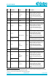
DA14531MOD SmartBond TINYTM Module Pin # J5 Pin Name P0_6 Preliminary Type DIO (Type A) Reset State Description I-PD INPUT/OUTPUT with selectable pull up/down resistors. Pull-down enabled during and after reset. General purpose I/O port bit or alternate function nodes. Contains state retention mechanism during power down. 1 Note J6 GND GND Ground J7 VBAT PWR POWER. Battery connection. IO supply. J8 P0_11 DIO (Type A) I-PD P0_10 J9 DIO (Type A) I-PD INPUT/OUTPUT.
DA14531MOD SmartBond TINYTM Module Pin # Pin Name J14 P0_5 J15 P0_9 J16 P0_8 Preliminary Type DIO (Type B) DIO (Type A) DIO (Type A) Reset State Description I-PD INPUT/OUTPUT with selectable pull up/down resistors. Pull-down enabled during and after reset. General purpose I/O port bit or alternate function nodes. Contains state retention mechanism during power down. I-PD INPUT/OUTPUT with selectable pull up/down resistors. Pull-down enabled during and after reset.
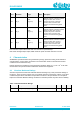
DA14531MOD SmartBond TINYTM Module 4.2 Preliminary Recommended Operating Conditions Table 3: Recommended Operating Conditions Parameter Description VBAT battery supply voltage enabling FLASH programming VPIN Conditions Min Typ Max Unit 1.65 3.3 V voltage on a pin -0.1 3.3 V TA ambient operating temperature -40 27 85 °C 4.
DA14531MOD SmartBond TINYTM Module Parameter Description IBAT_SLP_48KB battery supply current with system in extended sleep mode and all RAM retained IBAT_RF_RX battery supply current IBAT_RF_TX_+3 dBm IBAT_RF_TX_0d Bm IBAT_RF_TX_3dBm IBAT_RF_TX_7dBm IBAT_RF_TX_13dBm IBAT_RF_TX_19dBm Note 1 Preliminary Conditions Min Typ Max Unit 2.1 μA Continuous RX; FLASH in sleep mode; DCDC converter is on; 2.
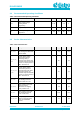
DA14531MOD SmartBond TINYTM Module Preliminary Table 7: Digital IO - DC Characteristics Parameter Description Conditions Min IIH HIGH level input current VI=VBAT_HIGH=3.0V IIL LOW level input current IIH_PD Typ Max Unit -10 10 μA VI=VSS=0V -10 10 μA HIGH level input current VI=VBAT=3.0V 60 180 μA IIL_PU LOW level input current VI=VSS=0V, VBAT=3.0V -180 -60 μA VOH HIGH level output voltage IO=3.5mA, VBAT=1.8V 0.8*VB AT VOL LOW level output voltage IO=3.5mA, VBAT=1.
DA14531MOD SmartBond TINYTM Module 5 5.1 Preliminary Mechanical Specifications Dimensions The module dimensions are presented in the following figure: Top view J1 J16 J16 J1 J2 J15 J15 J2 J3 J14 J14 J3 J4 J13 J13 J4 J5 J12 J12 J5 J11 Left side view Front view Right side view J10 J9 J8 J7 Common Dimensions J6 Rear view Bottom view Figure 3: Mechanical Drawing Datasheet CFR0011-120-00 Revision 2.
DA14531MOD SmartBond TINYTM Module 5.2 Preliminary PCB Footprint The footprint for the PCB is presented in the following figure: 12.5mm 9.5mm 10.15mm 14.5mm 0.9mm 1.5mm 1mm 1.75mm 2.0mm 2.0mm Figure 4: Module Footprint Top View 5.3 Marking Antenna Area J1 J16 J2 J15 J3 J4 J5 DA14531MOD-00F0100 yyww FCC ID: Y82-DA14531MOD IC:9576A- DA14531MOD ANATEL:05382-20-12967 J14 J13 J12 J6 J7 J8 J9 J10 J11 Figure 5: Module Shield Marking Datasheet CFR0011-120-00 Revision 2.
DA14531MOD SmartBond TINYTM Module 6 6.1 Preliminary Packaging Information Tape & Reel Figure 6: Tape and Reel The actual reel specification are presented in the following table: Table 9: Reel Specifications Datasheet CFR0011-120-00 Diameter 13 inch Reel tape width 24 inch Tape material Antistatic Qty/Reel 100/1000 pcs Leader 400 mm + 10% Trailer 160 mm + 10% Revision 2.
DA14531MOD SmartBond TINYTM Module 6.2 Preliminary Labeling Figure 7: Reel labeling 7 Application Information There are some special considerations regarding using the TINY module, namely: • RST signal is shared with the MOSI input of the NOR flash. For this reason, RST must not be driven to GND. When internal Flash is in use, reset functionality is not available. • The SPI Bus of DA14531 is used for the communication of the BLE SoC with the NOR Flash at boot time.
DA14531MOD SmartBond TINYTM Module Preliminary The PCB trace antenna radiated performance depends on the host PCB layout. Maximum antenna gain is better than -0.5 dBi when mounted on a 50x50 mm reference board, as illustrated in Figure 19. Radiation pattern is omnidirectional. The RF front end has been optimized to achieve the maximum possible efficiency for various mounting positions of the module on a host PCB.
DA14531MOD SmartBond TINYTM Module Preliminary Figure 9: Antenna Performance proximity with copper(left), laminate(middle) and laminate under antenna (right) The actual Tiny module evaluation board layout that has been used to conduct measurements is presented in the following figure: Figure 10: Tiny Module Evaluation Board 8.2 Antenna graphs Antenna VSWR measurements for the three mounting positions are described in the following figures. Datasheet CFR0011-120-00 Revision 2.
DA14531MOD SmartBond TINYTM Module Preliminary Figure 11: VSWR mounted in the upper left corner (Position #1) of evaluation board Figure 12: VSWR with module mounted in center (Position #2) of the evaluation board Figure 13: VSWR with module mounted in the upper right corner (Position #3) of the evaluation board 8.3 Radiation pattern The antenna radiation pattern measurements are carried out in an anechoic chamber.
DA14531MOD SmartBond TINYTM Module Preliminary Figure 14: Measurement plane definition Measurements are carried out for the module mounted in the upper right corner on the reference board with no laminate below antenna trace. Datasheet CFR0011-120-00 Revision 2.
DA14531MOD SmartBond TINYTM Module Preliminary Radiation pattern for antenna trace Horizontal polarization 9 Vertical polarization Figure 15: Radiation pattern for XY-plane, horizontal polarization. Figure 16: Radiation pattern for XY-plane, vertical polarization. Figure 17: Radiation pattern for XZ-plane, horizontal polarization. Figure 18: Radiation pattern for XZ-plane, vertical polarization. Figure 19: Radiation pattern for YZ-plane, horizontal polarization.
DA14531MOD SmartBond TINYTM Module Preliminary The volume of solder paste applied to the board is mainly determined by the aperture size and stencil thickness. An initial solder paste aperture for the pads is provided on the solder paste layer of the PCB footprint. This aperture is modified by the assembly process experts according to stencil thickness, solder paste and available assembly equipment. Solder profile depends on the solder paste type used.
DA14531MOD SmartBond TINYTM Module Preliminary 10 Ordering Information The ordering number consists of the part number followed by a suffix indicating the packing method. For details and availability, please consult your Dialog Semiconductor local sales representative. Table 12: Ordering Information (Samples) Part Number DA14531MOD-00F0100 Size (mm) Shipment Form Pack Quantity MOQ 12.5 x 14.5 x 2.
DA14531MOD SmartBond TINYTM Module Preliminary Area Item Service Standard Certificate ID Australia/New Zealand Wireless RCM Based on RED South Africa Wireless ICASA Based on RED TBD Brazil Wireless Anatel ATO No.14448/2017 Resolution No.680 05382-20-12967 China Wireless SRRC 信部无【2002】 353 Thailand Wireless NBTC NBTC TS 1035-2562 TBD RT 1768 11.
DA14531MOD SmartBond TINYTM Module Preliminary radiate radio frequency energy and, if not installed and used in accordance with the instructions, may cause harmful interference to radio communications. However, there is no guarantee that interference will not occur in a particular installation.
DA14531MOD SmartBond TINYTM Module Preliminary End-product labelling The DA14531 TINY MODULE is labelled with its own IC ID: 9576A-DA14531MOD. If the IC ID is not visible when the module is installed inside another device, then the outside of the end-product into which the module is installed must also display a label referring to the enclosed module. This exterior label can use the following or similar wording: “Contains IC ID: 9576A-DA14531MOD” 11.
DA14531MOD SmartBond TINYTM Module Preliminary 第十二條 經型式認證合格之低功率射頻電機,非經許可,公司、商號或使用者 均不得擅自變更頻率、加大功率或變更原設計之特性及功能。 第十四條 低功率射頻電機之使用不得影響飛航安全及干擾合法通信;經發現有 干擾現象時,應立即停用,並改善至無干擾時方得繼續使用。 前項合法通信,指依電信法規定作業之無線電通信。 低功率射頻電機須忍受合法通信或工業、科學及醫療用電波輻射性電 機設備之干擾。 End-product labelling The NCC ID can be applied directly on end-product's label. 11.6 MSIP (South Korea) R-R-Dlg-DA14531MOD DA14531 TINY MODULE has received certification of conformity in accordance with Radio Waves Act.
DA14531MOD SmartBond TINYTM Module Preliminary TA XXXX-YYYY APPROVED End-product may need to follow additional requirement according to regulation EMC 11.9 Brazil (Anatel) 05382-20-12967 The module has been tested and found to be compliant according to following Category II standards: • ATO (Act) No 14448/2017 End-product may need to follow additional requirement according to regulation EMC.
DA14531MOD SmartBond TINYTM Module Preliminary End-product may need to follow additional requirement according to regulation EMC. End-product labelling End-products will have their own ID and labelling requirements. 12 Environmental Information Dialog Semiconductor’s suppliers certify that its products are in compliance with the requirements of REACH and Directive 2015/863/EU of the European Parliament on the restriction of the use of certain hazardous substances in electrical and electronic equipment.
DA14531MOD SmartBond TINYTM Module Preliminary Revision History Revision Date Description 2.1 4-June-2020 Various updates ○ ○ ○ ○ Added Soldering Updated Regulatory information Updated PCB Footprint Updated Characteristics 1.2 18-May-2020 Initial target datasheet version ○ Various text updates ○ Electrical Characteristics update from mini-characterization 1.1 23-March-2020 ○ Initial target datasheet version Updated Regulatory Information section 1.
DA14531MOD SmartBond TINYTM Module Preliminary Status Definitions Revision Datasheet Status Product Status Definition 1. Target Development This datasheet contains the design specifications for product development. Specifications may be changed in any manner without notice. 2. Preliminary Qualification This datasheet contains the specifications and preliminary characterization data for products in pre-production.