INSTALLATION AND MAINTENANCE MANUAL ROADWAY SIGN LIGHT Document No: 9100-127-1480-99 Rev A MARCH 1, 2011 MODEL CODES Dialight Complete Fixtures RS5C4F-C (70W Cool White) see fig. 1-2 Dialight Complete Fixtures RS5C4K-C (100W Cool White) see fig. 1-2 Retrofit Cover Assemblies RS5C4F-H (70W Cool White) see fig. 3 Retrofit Cover Assemblies RS5C4K-H (100W Cool White) see fig. 3 Note: Dialight retro-fit cover assembly to fit Holophane Sign-Vue (supplied by others see page 5 for details.
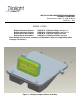
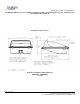
Document No: 9100-127-1480-99 Rev A Figure 1a: Dimensions: Side View of Dialight Complete Fixtures Figure 2: side View of Dialight Complete Fixture Page 2 of 10 1501 Route 34 South, Farmingdale, NJ 07727 Tel: (732) 919-3119 Fax: (732) 571-5778 www.dialight.
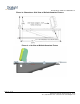
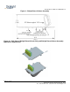
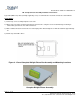
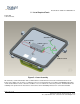
Document No: 9100-127-1480-99 Rev A Figure 3: Dialight Retro-fit Cover Assembly Figure 3a: Side View of Dialight Retro-fit Cover Only and Dialight Retro-fit Cover Assembly Mounted on SignVue Box Page 3 of 10 1501 Route 34 South, Farmingdale, NJ 07727 Tel: (732) 919-3119 Fax: (732) 571-5778 www.dialight.
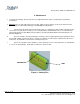
Document No: 9100-127-1480-99 Rev A 1: Introduction This sign light is designed for illumination of roadway sign structures. It uses the latest in solid state lighting technology for long life, low maintenance, and high efficiency. The unique optical design focuses light to where it is needed, giving improved efficiency over a conventional HID luminaire.
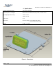
Document No: 9100-127-1480-99 Rev A The Dialight LED retro-fit cover assembly is intended to mount to Holophane Sign-Vue Series Luminaire boxes See additional box info below Holophane Sign-Vue Series Reference: Holophane drawing #fm-1751 CAD model SNVWD.dwg 11.13.08 Page 5 of 10 1501 Route 34 South, Farmingdale, NJ 07727 Tel: (732) 919-3119 Fax: (732) 571-5778 www.dialight.
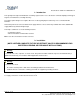
Document No: 9100-127-1480-99 Rev A 2A: Retrofit Cover Assembly Installation Instructions: 1) Open existing cover or lid assembly and discard. 2) Remove existing bulb and reflector assembly and discard per federal requirements. When cutting the existing wire connections, be sure to maximize the length remaining with the lower unit. 3) Manufacturer recommends but does not require the removal of existing ballast, transformer, and capacitor assemblies from existing unit.
Document No: 9100-127-1480-99 Rev A 2B: Complete fixture Assembly Installation Instructions: Type SSO (AWG 14-3) cable (normally supplied by user) is recommended for electrical connections to this luminaire. Flange Mount 1) Remove top cover assembly and place to the side. 2) Drill (3) 3/8” holes where shown in the bottom of the lower unit. Using these holes install housing to mounting to surface with (4) 5/16” bolts, nuts and lock washers. 3) Make conduit connection to lower unit.
Document No: 9100-127-1480-99 Rev A 3: Maintenance • To avoid personal injury, disconnect power to the light and allow the unit to cool down before performing maintenance. 1) Warning: No user serviceable parts inside of power supply enclosure. Risk of electric shock. Removal of the power supply cover will void the warranty, consult Dialight for authorization. a. Perform visual, mechanical and electrical inspections on a regular basis. We recommend routine checks to be made on a yearly basis.
Document No: 9100-127-1480-99 Rev A 4. Specifications Nominal AC Supply Voltage 120-277VAC, 50-60Hz Maximum power consumption 63W nominal or 100W nominal dependent on model chosen Operating temperature range -40°C to +55°C -40°F to +131°F Power factor >0.9 Dimensions Cover Assembly 7.3 H x 20 W x 20.5 D (in.) ………………………………………………………...24.6 24.6 H x 50.8 W x 52.1 (cm.) Weight 25 (lbs) 11.
Document No: 9100-127-1480-99 Rev A 5. List of Required Tools Power Drill 7/16 Hex Socket GROUND PIGTAIL OUTPUT WIRES POWER SUPPLY GROUND STRAP Figure 5: Cover Assembly All statements, technical information and recommendations contained herein are based on information and tests we believe to be reliable. The accuracy or completeness thereof is not guaranteed.