
Owner manual

Document No: 9100-127-1402-99 Rev A
Page 4 of 7
1501 Route 34 South, Farmingdale, NJ 07727
Tel: (732) 919-3119 Fax: (732) 751-5778 www.dialight.com
• Restore power and verify operation.
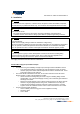
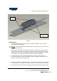
Figure 2.
Conduit through Mount
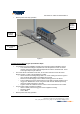
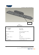
(Figure 3) Installation Steps:
• For maximum long term reliability and light output, the light must be installed in free air.
o The Linear fixture design incorporates an over-temperature control circuit that
reduces input power should internal temperatures reach a maximum level. In this
event, light output may be reduced.
• The Linear fixture is threaded for 3/4” NPT, at the center and each end of the Power
Supply Housing, in order to be assembled to conduit.
o Attach conduit and sealing fittings within .75” of the Housing as shown in figure 3.
Use conductive pipe sealant for all fittings and conduit.
o Remove the Power Supply Cover to attach incoming power to the fixture.
o Prior to replacing the Cover ensure that the o-ring seal is properly seated in the o-
ring groove. Reattach the Cover using the screws and lock washers previously
removed. Tighten all screws to 15 in/lbs.
o Tighten 1/4-20 anti-rotational screw in order to secure the fixture to the conduit.
• Connect power cable conductors as follows:
o Green to Safety Ground using green screw supplied in housing.
o Neutral to White
o Line to Black
• Restore power and verify operation.
Sealing
fitting
Anti-rotation
screw
Power
Supply
Cover