Series 52 52/XR MADI Router Manual © 2008 DHD Deubner Hoffmann Digital GmbH Version: 1.8.
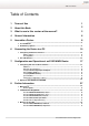
Table of Contents Table of Contents 1 Terms of Use 1 2 About this Book 2 3 What is new in this version of the manual? 3 4 General Information 6 5 Assemble a Device 8 ................................................................................................................................... 8 1 List of Modules ...................................................................................................................................
Series 52 - 52/XR MADI Router Manual 52-6129A ......................................................................................................................................................... - XR Dual MADI Module, multi/single 52-5310A ......................................................................................................................................................... - MB/XD/XR GPIO Module, 8 out, 4 in 52-5311A ...................................................................
Terms of Use 1 1 Terms of Use Series 52 52/XR MADI Router Manual © 2008 DHD Deubner Hoffmann Digital GmbH This manual is copyright of DHD. It might be distributed and copied as long as it is copied completely as a whole and this copyright notice is included. No part of this document may be copied or distributed without prior written permission of DHD Deubner Hoffmann Digital GmbH. Windows is a registered trademark of Microsoft Corp., Redmond, Wash., USA.
2 Series 52 - 52/XR MADI Router Manual 2 About this Book This manual refers to the Toolbox5, Version 6.3.5, the DHD Operation Manager, Version 1.2.5 and the DHD Operation Server, Version 1.2.4 This manual will provide you a comprehensive overview about the applications of an 52/XR MADI Router and explains its configuration. The content of this manual is subject to change without notice.
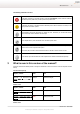
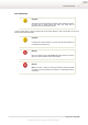
About this Book 3 The Meaning of Advices in the Text Warning The demands and advices in this fields should be followed unconditional, because otherwise hardware and software products, data bases, as well as persons may suffer a loss. Important The demands and advices in this fields should be followed, because these contents are necessary for the proper operation of the DHD systems. Note Recommendations and further information are marked as notes.
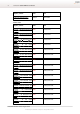
4 Series 52 - 52/XR MADI Router Manual Chapter / Section State Note Configuring MADI Redundancy changed Picture added. State Note Version 1.5.0: Chapter / Section 52-5310A - MB/XD/XR GPIO Module, added 8 out,4 in Pin assignment. 52-5311A - MB/XD/XR GPIO Module, added 8 out,4 in Pin assignment. 52-6710A - XR Router/DSP Sync. added Module Pin assignment. 52-6720A Monitoring Pin assignment. - XR True Output added 52-6120A - XR Dual MADI Module, added multimode Meaning of the LEDs.
What is new in this version of the manual? 5 Version 1.4.0 and before: No changelog available. Version 1.8.0 - 16.06.2008 Änderungen vorbehalten / Subject to change without notice.
6 Series 52 - 52/XR MADI Router Manual 4 General Information Safety Instructions Ignoring the following safety instructions may lead to accidents with severe, life-threatening injuries, caused by fire or electric shocks. Always act according to the directions of this manual. Fix the device well in a rack or studio furniture with the mounting orientation given by DHD. Only connect the power cable of the device to a socket, which carries the voltage stated on the specification plate.
General Information 7 Care Instructions Important The cleaning of a device should be done in Off-Air mode as possible. That means the device does not handle relevant audio and/or logic signals that are integrated in the current broadcasting process. To clean your DHD device, in general a soft, lint-free and dry cloth is sufficient. In case of severe soiling, you can use a damp cloth and household detergent.
8 Series 52 - 52/XR MADI Router Manual 5 Assemble a Device Every device is getting assembled individual depending on your special needs. Therefore, different hardware modules, as well as configuration and control software applications are available. If you need help to define your requirements for an 52/XR, please contact your local DHD partner. 5.
Assemble a Device 9 Tip We recommend to feed power supplies from different mains supply systems to prevent power failures. The 52/XR MADI Router can optional be operated with two power supplies of the type 52-5048 (48V/200W). Sync Module Redundancy An 52/XR MADI Router can be equipped with a redundant synchronisation module. Thus, the device becomes more reliable concerning the internal and external synchronisation.
10 Series 52 - 52/XR MADI Router Manual 6 Connecting the Device to a PC The configuration of an 52/XR MADI Router is done with the aid of a PC. Usually an ethernet interface is employed for this connection. The next section describes how to configure and use this interface of the communication controller. In addition to the ethernet interface, each controller module has an USB interface.
Connecting the Device to a PC 11 The subnet mask is automatically set to 255.0.0.0, according to the classification of this IP range. Thus the following IP basic setting results for the example device: · IP address: 10.16.0.2 · Subnet mask: 255.0.0.0 Please learn in the following chapter how to change these settings and adjust them to your IT environment. 6.1.
12 Series 52 - 52/XR MADI Router Manual The Network Config window shows the current IP configuration of the device with the serial number which is entered in the Serial No text field. Serial No - The Serial Number The device of which you can see the network settings, is always represented by its serial number (Serial No). This serial number is unambiguous and is only valid for one single controller. You can use the field to read out settings of devices that are located in a different network segment.
Connecting the Device to a PC 13 Mail Server This text field has no function yet and does not need to be filled in. Time Server Series 52 systems run with an internal system time which can be synchronised to a time server (NTP - Network Time Protocol). For this, please enter the IP address of your time server in the text field Time Server. If you cannot see the device in the list (b) 1. Click on the Device command in the menu. 2. Select the Network Config... command from this menu. 3.
14 Series 52 - 52/XR MADI Router Manual 6.2 The USB Interface You can connect 52/XR MADI Router devices to a PC via USB. The 52-6850 and 52-6851 modules have an according USB interface (B type, USB 2.0). Use the interface for instance in case you do not want an ethernet connection or if you want to locally connect a PC to the 52/XR MADI Router for maintenance purposes. In order to use the USB interface of the 52/ XR MADI Router, first you have to install a driver on your PC.
Connecting the Device to a PC 15 Step 2: Setting the path. Enter the drive and if necessary the folders, to define the path to the file MX-XR_usb-install.inf and click Next. Step 3: Installing the driver. Version 1.8.0 - 16.06.2008 Änderungen vorbehalten / Subject to change without notice.
16 Series 52 - 52/XR MADI Router Manual The driver now gets installed. Step 4: Finish the installation. Finally the "Found New Hardware Wizard" will tell you that it has finished the installation and you can end the process by clicking the Finish button. From now on you can communicate with the device via the USB interface. The device manager of the Windows (TM) control panel. After the driver has been installed properly, the connection to the USB interface is simulated as a network connection.
Connecting the Device to a PC 17 Please contact your IT department or your administrator if you need help to install the driver. 7 Configuration and Operation of an 52/XR MADI Router 7.1 Configuring with the Toolbox5 Software The configuration software is represented by a executable file named Toolbox5.exe. Double click the file Toolbox5. exe to start the application. Note In this manual only the most important steps to configure an 52/XR MADI Router with the Toolbox5 software are mentioned.
18 Series 52 - 52/XR MADI Router Manual After the software has started, it displays an empty project list and some basic project properties, which can be customized. The Toolbox5 application window right after startup. From here on, you have two ways to proceed: 1. You can create a new project to setup one or several routing devices from scratch. 2. You can load an existing project file (*.dp5) from your PC to edit the configuration of the existing devices.
Configuration and Operation of an 52/XR MADI Router 7.1.1 19 Add Devices Below the project tree you can find the Add... button. A menu with devices - which can be added to the project appears after clicking this button. Choose the entry Add 52/XR Router from this menu to add an 52/XR routing device to the project. Press Remove if you want to delete a device of the project tree.
20 Series 52 - 52/XR MADI Router Manual 7.1.2 DSP Frame I/O Configuration Click onto the + sign in front of the device label to reach the sub-branches of the device configuration. On the DSP Frame I/O tab, the hardware layout of the routing device can be configured. The selected frame size influences the number of configurable inputs and outputs in the Toolbox5, but it has no direct influence concerning the functionality of the hardware.
Configuration and Operation of an 52/XR MADI Router 21 Important You need at least 3 modules to operate an 52/XR MADI Router. These modules are inserted into the DSP Frame I/O layout by default. · Slot 1: 52-6710 Sync Module · Slot 2: 52-6850 Communication Controller · Slot 9: 52-6440 Router Kernel You are allowed to change the type of the preconfigured router kernel (type 52-6442 supports 2048 channels, type 52-6440 supports 4096 channels), but at least one routing kernel is necessary for operation.
22 Series 52 - 52/XR MADI Router Manual 7.1.3 Configure and Label Single Inputs and Outputs Click onto the + sign in front of the DSP Frame I/O branch and select an existing port to reach the channel configuration. If the Number of Channels is set to 64 or 56, you can switch channels to mono or stereo and set a label for each single input and output here. Additionally, you can set a local level adjustment for single inputs and outputs, which differs from the global settings.
Configuration and Operation of an 52/XR MADI Router 7.1.4 23 Linked 52/MB at a MADI Port If a MADI port was linked to an 52/MB MADI Breakout System, you are able to define the layout of the connected 52/MB device here. Basically, this part of the configuration is to make the whole configuration process easier. The 52/MB hardware itself must not be configured. I/O configuration of a linked 52/MB.
24 Series 52 - 52/XR MADI Router Manual 7.1.5 Configuring MADI Redundancy Slot 13 to 18 (and slot 34 to 39 in a 6 HU frame) can be operated in a normal or a redundant mode. If switched to redundant, a MADI port duplicates the signals of the corresponding port on the left side of the router backplane. Choose Enabled in the column Redundancy at the DSP Frame I/O to define the respective MADI port as redundant.
Configuration and Operation of an 52/XR MADI Router 7.1.6 25 Synchronisation Selecting the Audio branch, displays the synchronisation window. Here you can do refinements on the current device synchronisation. It is possible, to configure two independent synchronisation sources. Sync Source 1 is always meant to be the master sync source and is used by the system as long as it is available.
26 Series 52 - 52/XR MADI Router Manual 7.1.7 Transferring a Configuration to a Device If you want to transfer a configuration to a device, please follow these steps: · Select the desired device from the projects device tree. · Click onto the symbol in the toolbar or choose Load to Device in the Transfer menu. The DHD Connection Dialog appears. · Select the desired hardware from the list and press OK. The transfer process starts and the configuration is copied to the chosen hardware.
Configuration and Operation of an 52/XR MADI Router 8 Further Information 8.1 Maintenance 27 For maintenance purposes the DHD Maintenance software is provided. Start the application by double clicking the file MTN5.exe. It also possible to open the maintenance window in the Toolbox5 software. Therefore, choose the command Maintenance Window of the View menu or just press the key F7.
28 Series 52 - 52/XR MADI Router Manual Confirming the firmware upload. 4. The updating process starts after pressing Yes. A progress bar is shown during the process, which will only take a few seconds. The progress bar during the firmware upload. 5. After successfully uploading the file, you will be asked to reset the system. The system loads the new operating software after a restart. Confirming the reset. Important A reset will interrupt the audio process of the system for a short period of time.
Further Information 8.2 I/O Module Pin Assignment 8.2.1 52-5310A - MB/XD/XR GPIO Module, 8 out,4 in 29 Pin out for the 52-5310 Module. Version 1.8.0 - 16.06.2008 Änderungen vorbehalten / Subject to change without notice.
30 Series 52 - 52/XR MADI Router Manual 8.2.2 52-5311A - MB/XD/XR GPIO Module, 8 out,4 in Pin out for the 52-5311 Module. © 2008 DHD Deubner Hoffmann Digital GmbH Änderungen vorbehalten / Subject to change without notice.
Further Information 8.2.3 31 52-5320A - XD/XR GPIO Module, 16 out, 4 in Pin out for the 52-5320 Module. Version 1.8.0 - 16.06.2008 Änderungen vorbehalten / Subject to change without notice.
32 Series 52 - 52/XR MADI Router Manual 8.2.4 52-6710A - XR Router/DSP Sync. Module Pin out for the 52-6710 Module. © 2008 DHD Deubner Hoffmann Digital GmbH Änderungen vorbehalten / Subject to change without notice.
Further Information 8.2.5 33 52-6720A - XR True Output Monitoring Pin out for the 52-6720 Module. Version 1.8.0 - 16.06.2008 Änderungen vorbehalten / Subject to change without notice.
34 Series 52 - 52/XR MADI Router Manual 8.3 Meaning of the LEDs 8.3.1 52-6120A - XR Dual MADI Module, multimode Meaning of the LEDs of the 52-6120 Module. 1. This LED is permanently on if the module is powered. 2. Indicates, that the module is running. This LED blinks. Seen from left to right over the entire system, these LEDs should blink as a moving light. 3. LED 3 indicates, that routing kernel no. 1 is sending data to the outputs of the upper MADI port.
Further Information 35 is operating now. 8. Normally, the first kernel should send data to the outputs of the lower MADI port. If the first kernel is malfunctioning, LED 8 indicates, that routing kernel no. 2 is sending data to the outputs of the lower MADI port. 9. The LED indicates, that routing kernel no. 1 is locked to the inputs of the lower MADI port. 10. If a redundant kernel is installed, this LED indicates, that routing kernel no. 2 is locked to the inputs of the lower MADI port. 8.3.
36 Series 52 - 52/XR MADI Router Manual 5. The LED indicates, that routing kernel no. 1 is locked to the inputs of the upper MADI port. 6. If a redundant kernel is installed, this LED indicates, that routing kernel no. 2 is locked to the inputs of the upper MADI port. 7. LED 7 indicates, that routing kernel no. 1 is sending data to the outputs of the lower MADI port. This LED is blinking if the first kernel starts malfunctioning.
Further Information 37 3. LED 3 indicates, that routing kernel no. 1 is sending data to the outputs of the upper MADI port. This LED is blinking if the first kernel starts malfunctioning. That means, the first kernel should send data to the outputs of the upper MADI port, but it does not. If a second, redundant routing kernel is available, LED 4 indicates, that the second routing kernel is operating now. 4. Normally, the first kernel should send data to the outputs of the upper MADI port.
38 Series 52 - 52/XR MADI Router Manual 8.3.4 52-5310A - MB/XD/XR GPIO Module, 8 out, 4 in Meaning of the LEDs of the 52-5310 Module. 1. This LED is permanently on if the module is powered. 2. Indicates, that the module is running. This LED blinks. Seen from left to right over the entire system, these LEDs should blink as a moving light. © 2008 DHD Deubner Hoffmann Digital GmbH Änderungen vorbehalten / Subject to change without notice.
Further Information 8.3.5 39 52-5311A - MB/XD/XR GPIO Module, 8 out, 4 in Meaning of the LEDs of the 52-5311 Module. 1. This LED is permanently on if the module is powered. 2. Indicates, that the module is running. This LED blinks. Seen from left to right over the entire system, these LEDs should blink as a moving light. Version 1.8.0 - 16.06.2008 Änderungen vorbehalten / Subject to change without notice.
40 Series 52 - 52/XR MADI Router Manual 8.3.6 52-5320A - XD/XR GPIO Module, 16 out, 4 in Meaning of the LEDs of the 52-5311 Module. 1. This LED is permanently on if the module is powered. 2. Indicates, that the module is running. This LED blinks. Seen from left to right over the entire system, these LEDs should blink as a moving light. © 2008 DHD Deubner Hoffmann Digital GmbH Änderungen vorbehalten / Subject to change without notice.
Further Information 8.3.7 41 52-6440A - XR Router/DSP Kernel Module 4096 Meaning of the LEDs of the 52-6440 Module. 1. This LED is permanently on if the module is powered. 2. This LED shows the hardware status and is permanently on if the boot process of the programmable logic was successfully done. 3. This LED indicates the DSP usage. The more the LED glows, the more DSP power is used. 4. Indicates, that the module is running. This LED blinks.
42 Series 52 - 52/XR MADI Router Manual 8.3.8 52-6442A - XR Router/DSP Kernel Module 2048 Meaning of the LEDs of the 52-6442 Module. 1. This LED is permanently on if the module is powered. 2. This LED shows the hardware status and is permanently on if the boot process of the programmable logic was successfully done. 3. This LED indicates the DSP usage. The more the LED glows, the more DSP power is used. 4. Indicates, that the module is running. This LED blinks.
Further Information 8.3.9 43 52-6850A - XR Comm. Controller, red. Meaning of the LEDs of the 52-6850 Module. 1. Indicates, that the module is running. This LED blinks. Seen from left to right over the entire system, these LEDs should blink as a moving light. 2. The LED flashes if data is transmitted or received via the upper RJ45 port. 3. The LED is on if the communication controller is connected to the controller network via the middle RJ45 connector. It flashes if data is received. 4.
44 Series 52 - 52/XR MADI Router Manual 8.3.10 52-6851A - XR Communication Controller Meaning of the LEDs of the 52-6851 Module. 1. Indicates, that the module is running. This LED blinks. Seen from left to right over the entire system, these LEDs should blink as a moving light. 2. This LED is momentary unused and is reserved for future functions. 3. The LED is on if the communication controller is connected to the controller network via the middle RJ45 connector. It flashes if data is received. 4.
Further Information 45 8.3.11 52-6710A - XR Router/DSP Sync. Module Meaning of the LEDs of the 52-6710 Module. 1. This LED is permanently on if the module is powered. 2. Indicates, that the module is running. This LED blinks. Seen from left to right over the entire system, these LEDs should blink as a moving light. 3. Indicates, that the primary sync is active.
46 Series 52 - 52/XR MADI Router Manual sync module) is locked. 8.3.12 52-6720A - XR True Output Monitoring Meaning of the LEDs of the 52-6720 Module. 1. This LED is permanently on if the module is powered. 2. Indicates, that the module is running. This LED blinks. Seen from left to right over the entire system, these LEDs should blink as a moving light. 8.
47 Further Information AnAudio Router Samples -An DigRouter -An AnRouter -Dig DigDigSRC- DigSRCRouter Router Router -Dig -Dig -DigSRC Routing Kernel, general delay 4 4 4 4 4 4 4 52/MB and 52/CR input, general delay 10 10 10 10 10 10 10 52/MB and 52/CR output, general delay 10 10 10 10 10 10 10 12 12 29 29 48 48 AD converter CS5361, component dependent delay DA converter PCM1793, component dependent delay SRC AD1895 input, component dependent delay SRC AD1895 output, compo
48 Series 52 - 52/XR MADI Router Manual 8.5 Example of Use In the following drawing, you can find an example how to integrate an 52/XR MADI Router into an audio network. Series 52 audio network with an 52/XR MADI Router and 52/MX consoles. In this example an 52/XR MADI Router is located in the machine room. The router is connected to the mixing consoles in the studios (Control Room 1, Control Room 2 and News) via MADI.
Index 49 Index A 3 32bit float 20 5 52/MB 23 52/MB at a MADI Port 23 52-5048A - Power Supply Module 48V / 200W 8 52-5310A - MB/XD/XR GPIO Module, 8 out,4 in 29, 38 52-5311A - MB/XD/XR GPIO Module, 8 out,4 in 30, 39 52-5860A - XD/XR RS232/RS422 Extender 8 52-5862A - XD/XR RS232/RS232 Extender 8 52-6063A - XR Router/DSP Frame 3U, empty 8 52-6066A - XR Router/DSP Frame 6U, empty 8 52-6120A - XR Dual MADI Module, multimode 8, 34 52-6125A - XR Dual MADI Module, single mode 8, 35 52-6129A - XR Dual MADI Modul
50 Series 52 F N Firmware Update 27 Fixed 11 Fixed IP Setting 11 Network Config 11 Network Time Protocol 11 NTP 11 Number of Channels 22 H Hardware Name Headroom 20 O 11 Operation with DHDOS and DHDOM I P I/O Frames 8 I/O Modules 8 IEEE 802.
Index 51 T Terms of Use 1 The Device Name 11 The Serial Number 11 Time Server 11 Toolbox5 17 transfer rate 10 Transferring a Configuration to a Device 26 U Update Firmware 27 USB Interface 14 V VariSpeed View menu 25 11 © 2008 DHD Deubner Hoffmann Digital GmbH