
Data Sheet


CP2102
14 Rev. 1.4
8. Voltage Regulator
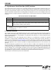
The CP2102 includes an on-chip 5 to 3 V voltage regulator. This allows the CP2102 to be configured as either a
USB bus-powered device or a USB self-powered device. These configurations are shown in Figure 6 and Figure 7.
When enabled, the 3 V voltage regulator output appears on the V
DD
pin and can be used to power external 3 V
devices. See Table 10 for the voltage regulator electrical characteristics.
Alternatively, if 3 V power is supplied to the V
DD
pin, the CP2102 can function as a USB self-powered device with
the voltage regulator disabled. For this configuration, it is recommended that the REGIN input be tied to the 3 V net
to disable the voltage regulator. This configuration is shown in Figure 8.
The USB max power and power attributes descriptor must match the device power usage and configuration. See
application note “AN144: CP210x Customization Guide” for information on how to customize USB descriptors for
the CP2102.
Note: It is recommended that additional decoupling capacitance (e.g., 0.1 µF in parallel with 1.0 µF) be provided on the REGIN
input.
Figure 6. Configuration 1: USB Bus-Powered
Table 10. Voltage Regulator Electrical Specifications
–40 to +85 °C unless otherwise specified.
Parameter Conditions Min Typ Max Units
Input Voltage Range
4.0 — 5.25 V
Output Voltage
Output Current = 1 to 100 mA* 3.0 3.3 3.6 V
VBUS Detection Input Threshold
1.0 1.8 2.9 V
Bias Current
—90—µA
*Note: The maximum regulator supply current is 100 mA.
Voltage Regulator (REG0)5 V In
3 V Out
VBUS Sense
REGIN
VBUS
From VBUS
To 3 V
Power Net
Device
Power Net
V
DD
CP2102