
Data Sheet
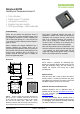


Datasheet SHT20
www.sensirion.com Version 3 – December 2011 9/14
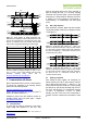
Resolution
RH typ
RH max
T typ
T max
Units
14 bit
66
85
ms
13 bit
33
43
ms
12 Bit
22
29
17
22
ms
11 bit
12
15
9
11
ms
10 bit
7
9
ms
8 bit
3
4
ms
Table 7 Measurement times for RH and T measurements at
different resolutions. Typical values are recommended for
calculating energy consumption while maximum values shall be
applied for calculating waiting times in communication.
Please note: I
2
C communication allows for repeated Start
conditions (S) without closing prior sequence with Stop
condition (P) – compare Figures 15, 16 and 18. Still, any
sequence with adjacent Start condition may alternatively
be closed with a Stop condition.
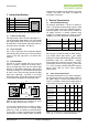
5.5 Soft Reset
This command (see Table 6) is used for rebooting the
sensor system without switching the power off and on
again. Upon reception of this command, the sensor
system reinitializes and starts operation according to the
default settings – with the exception of the heater bit in the
user register (see Sect. 5.6). The soft reset takes less than
15ms.
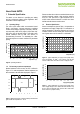
1
2
3
4
5
6
7
8
9
10
11
12
13
14
15
16
17
18
S
1
0
0
0
0
0
0
0
ACK
1
1
1
1
1
1
1
0
ACK
P
I
2
C address + write
Soft Reset
Figure 17 Soft Reset – grey blocks are controlled by SHT2x.
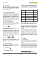
5.6 User Register
The content of User Register is described in Table 8.
Please note that reserved bits must not be changed and
default values of respective reserved bits may change
over time without prior notice. Therefore, for any writing to
the User Register, default values of reserved bits must be
read first. Thereafter, the full User Register string is
composed of respective default values of reserved bits
and the remainder of accessible bits optionally with default
or non-default values.
The end of battery alert is activated when the battery
power falls below 2.25V.
The heater is intended to be used for functionality
diagnosis – relative humidity drops upon rising
temperature. The heater consumes about 5.5mW and
provides a temperature increase of about 0.5 – 1.5°C.
OTP Reload is a safety feature and loads the entire OTP
settings to the register, with the exception of the heater bit,
before every measurement. This feature is disabled per
default and is not recommended for use. Please use Soft
Reset instead – it contains OTP Reload.
Bit
# Bits
Description / Coding
Default
7, 0
2
Measurement resolution
RH
T
„00‟
12 bit
14 bit
„01‟
8 bit
12 bit
„10‟
10 bit
13 bit
„11‟
11 bit
11 bit
„00‟
6
1
Status: End of battery
14
„0‟: VDD > 2.25V
„1‟: VDD < 2.25V
„0‟
3, 4, 5
3
Reserved
2
1
Enable on-chip heater
„0‟
1
1
Disable OTP Reload
„1‟
Table 8 User Register. Cut-off value for End of Battery signal
may vary by ±0.1V. Reserved bits must not be changed. “OTP
reload” = „0‟ loads default settings after each time a
measurement command is issued.
An example for I
2
C communication reading and writing the
User Register is given in Figure 18.
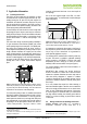
1
2
3
4
5
6
7
8
9
10
11
12
13
14
15
16
17
18
S
1
0
0
0
0
0
0
0
ACK
1
1
1
0
0
1
1
1
ACK
I
2
C address + write
Read Register
19
20
21
22
23
24
25
26
27
28
29
30
31
32
33
34
35
36
S
1
0
0
0
0
0
0
1
ACK
0
0
0
0
0
0
1
0
NACK
I
2
C address + read
Register content
37
38
39
40
41
42
43
44
45
46
47
48
49
50
51
52
53
54
S
1
0
0
0
0
0
0
0
ACK
1
1
1
0
0
1
1
0
ACK
I
2
C address + write
Write Register
55
56
57
58
59
60
61
62
63
0
0
0
0
0
0
1
1
ACK
P
Register content to be written
Figure 18 Read and write register sequence – grey blocks are
controlled by SHT2x. In this example, the resolution is set to 8bit
/ 12bit.
5.7 CRC Checksum
SHT21 provides a CRC-8 checksum for error detection.
The polynomial used is x
8
+ x
5
+ x
4
+1. For more details
and implementation please refer to the application note
“CRC Checksum Calculation for SHT2x”.
14
This status bit is updated after each measurement