
Data Sheet


Datasheet SHT20
www.sensirion.com Version 3 – December 2011 8/14
Command
Comment
Code
Trigger T measurement
hold master
1110‟0011
Trigger RH measurement
hold master
1110‟0101
Trigger T measurement
no hold master
1111‟0011
Trigger RH measurement
no hold master
1111‟0101
Write user register
1110‟0110
Read user register
1110‟0111
Soft reset
1111‟1110
Table 6 Basic command set, RH stands for relative humidity,
and T stands for temperature
Hold master or no hold master modes are explained in
next Section.
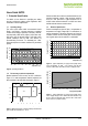
5.4 Hold / No Hold Master Mode
There are two different operation modes to communicate
with the sensor: Hold Master mode or No Hold Master
mode. In the first case the SCL line is blocked (controlled
by sensor) during measurement process while in the latter
case the SCL line remains open for other communication
while the sensor is processing the measurement. No hold
master mode allows for processing other I
2
C
communication tasks on a bus while the sensor is
measuring. A communication sequence of the two modes
is displayed in Figure 15 and Figure 16, respectively.
In the hold master mode, the SHT2x pulls down the SCL
line while measuring to force the master into a wait state.
By releasing the SCL line the sensor indicates that internal
processing is terminated and that transmission may be
continued.
1
2
3
4
5
6
7
8
9
10
11
12
13
14
15
16
17
18
S
1
0
0
0
0
0
0
0
ACK
1
1
1
0
0
1
0
1
ACK
I
2
C address + write
Command (see Table 6)
19
20
21
22
23
24
25
26
27
S
1
0
0
0
0
0
0
1
ACK
Measurement
I
2
C address + read
Hold during measurement
28
29
30
31
32
33
34
35
36
37
38
39
40
41
42
43
44
45
0
1
1
0
0
0
1
1
ACK
0
1
0
1
0
0
1
0
ACK
Data (MSB)
Data (LSB)
Stat.
46
47
48
49
50
51
52
53
54
0
1
1
0
0
1
0
0
NACK
P
Checksum
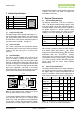
Figure 15 Hold master communication sequence – grey blocks
are controlled by SHT2x. Bit 45 may be changed to NACK
followed by Stop condition (P) to omit checksum transmission.
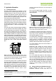
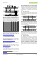
In no hold master mode, the MCU has to poll for the
termination of the internal processing of the sensor. This is
done by sending a Start condition followed by the I
2
C
header (1000‟0001) as shown in Figure 16. If the internal
processing is finished, the sensor acknowledges the poll of
the MCU and data can be read by the MCU. If the
measurement processing is not finished the sensor
answers no ACK bit and the Start condition must be
issued once more.
For both modes, since the maximum resolution of a
measurement is 14 bit, the two last least significant bits
(LSBs, bits 43 and 44) are used for transmitting status
information. Bit 1 of the two LSBs indicates the
measurement type („0‟: temperature, „1‟ humidity). Bit 0 is
currently not assigned.
1
2
3
4
5
6
7
8
9
10
11
12
13
14
15
16
17
18
S
1
0
0
0
0
0
0
0
ACK
1
1
1
1
0
1
0
1
ACK
I
2
C address + write
Command (see Table 6)
19
20
21
22
23
24
25
26
27
Measurement
S
1
0
0
0
0
0
0
1
NACK
measuring
I
2
C address + read
19
20
21
22
23
24
25
26
27
Measurement
S
1
0
0
0
0
0
0
1
ACK
continue measuring
I
2
C address + read
28
29
30
31
32
33
34
35
36
37
38
39
40
41
42
43
44
45
0
1
1
0
0
0
1
1
ACK
0
1
0
1
0
0
1
0
ACK
Data (MSB)
Data (LSB)
Stat.
46
47
48
49
50
51
52
53
54
0
1
1
0
0
1
0
0
NACK
P
Checksum
Figure 16 No Hold master communication sequence – grey
blocks are controlled by SHT2x. If measurement is not
completed upon “read” command, sensor does not provide ACK
on bit 27 (more of these iterations are possible). If bit 45 is
changed to NACK followed by Stop condition (P) checksum
transmission is omitted.
In the examples given in Figure 15 and Figure 16 the
sensor output is S
RH
= „0110‟0011‟0101‟0000‟. For the
calculation of physical values Status Bits must be set to „0‟
– see Chapter 6.
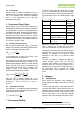
The maximum duration for measurements depends on the
type of measurement and resolution chosen – values are
displayed in Table 7. Maximum values shall be chosen for
the communication planning of the MCU.