
Data Sheet


Datasheet SHT20
www.sensirion.com Version 3 – December 2011 7/14
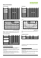
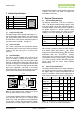
Figure 12 Timing Diagram for Digital Input/Output Pads,
abbreviations are explained in Table 5. SDA directions are seen
from the sensor. Bold SDA line is controlled by the sensor, plain
SDA line is controlled by the micro-controller. Note that SDA
valid read time is triggered by falling edge of anterior toggle.
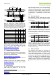
Parameter
min
typ
max
Units
SCL frequency, f
SCL
0
-
0.4
MHz
SCL High Time, t
SCLH
0.6
-
-
µs
SCL Low Time, t
SCLL
1.3
-
-
µs
SDA Set-Up Time, t
SU
100
-
-
ns
SDA Hold Time, t
HD
0
-
900
ns
SDA Valid Time, t
VD
0
-
400
ns
SCL/SDA Fall Time, t
F
0
-
100
ns
SCL/SDA Rise Time, t
R
0
-
300
ns
Capacitive Load on Bus Line, C
B
0
-
400
pF
Table 5 Timing specifications of digital input/output pads for I
2
C
fast mode. Entities are displayed in Figure 12. VDD = 2.1V to
3.6V, T = -40°C to 125°C, unless otherwise noted. For further
information regarding timing, please refer to
http://www.standardics.nxp.com/support/i2c/.
5 Communication with Sensor
SHT20 communicates with I
2
C protocol. For information on
I
2
C beyond the information in the following Sections
please refer to the following website:
http://www.standardics.nxp.com/support/i2c/.
Please note that all sensors are set to the same I
2
C
address, as defined in Section 5.3.
13
Furthermore, please note, that Sensirion provides an
exemplary sample code on its home page – compare
www.sensirion.com/SHT20.
5.1 Start Up Sensor
As a first step, the sensor is powered up to the chosen
supply voltage VDD (between 2.1V and 3.6V). After
13
For sensors with alternative I
2
C address please contact Sensirion via
info@sensirion.com.
power-up, the sensor needs at most 15ms, while SCL is
high, for reaching idle state, i.e. to be ready accepting
commands from the master (MCU). Current consumption
during start up is 350µA maximum. Whenever the sensor
is powered up, but not performing a measurement or
communicating, it is automatically in idle state (sleep
mode).
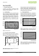
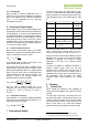
5.2 Start / Stop Sequence
Each transmission sequence begins with Start condition
(S) and ends with Stop condition (P) as displayed in Figure
13 and Figure 14.
Figure 13 Transmission Start condition (S) - a high to low
transition on the SDA line while SCL is high. The Start condition
is a unique state on the bus created by the master, indicating to
the slaves the beginning of a transmission sequence (bus is
considered busy after a Start).
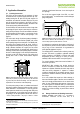
Figure 14 Transmission Stop condition (P) - a low to high
transition on the SDA line while SCL is high. The Stop condition
is a unique state on the bus created by the master, indicating to
the slaves the end of a transmission sequence (bus is
considered free after a Stop).
5.3 Sending a Command
After sending the Start condition, the subsequent I
2
C
header consists of the 7-bit I
2
C device address „1000‟000‟
and an SDA direction bit (Read R: „1‟, Write W: „0‟). The
sensor indicates the proper reception of a byte by pulling
the SDA pin low (ACK bit) after the falling edge of the 8
th
SCL clock. After the issue of a measurement command
(„1110‟0011‟ for temperature, „1110‟0101‟ for relative
humidity‟), the MCU must wait for the measurement to
complete. The basic commands are summarized in Table
6.
SCL
70%
30%
t
SCLL
1/f
SCL
t
SCLH
t
R
t
F
SDA
70%
30%
t
SU
t
HD
SDA valid read
DATA IN
t
R
SDA
70%
30%
DATA OUT
t
VD
t
F
SDA valid write
SDA
SCL
70%
30%
70%
30%
SDA
SCL
70%
30%
70%
30%