
Data Sheet


Datasheet SHT20
www.sensirion.com Version 3 – December 2011 6/14
3 Interface Specifications
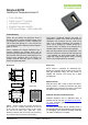
Pin
Name
Comment
1
SDA
Serial Data, bidirectional
2
VSS
Ground
5
VDD
Supply Voltage
6
SCL
Serial Clock, bidirectional
3,4
NC
Not Connected
Table 2 SHT2x pin assignment, NC remain floating (top view)
3.1 Power Pins (VDD, VSS)
The supply voltage of SHT2x must be in the range of 2.1 –
3.6V, recommended supply voltage is 3.0V. Power supply
pins Supply Voltage (VDD) and Ground (VSS) must be
decoupled with a 100nF capacitor, that shall be placed as
close to the sensor as possible – see Figure 11.
3.2 Serial clock (SCL)
SCL is used to synchronize the communication between
microcontroller (MCU) and the sensor. Since the interface
consists of fully static logic there is no minimum SCL
frequency.
3.3 Serial SDA (SDA)
The SDA pin is used to transfer data in and out of the
sensor. For sending a command to the sensor, SDA is
valid on the rising edge of SCL and must remain stable
while SCL is high. After the falling edge of SCL the SDA
value may be changed. For safe communication SDA shall
be valid t
SU
and t
HD
before the rising and after the falling
edge of SCL, respectively – see Figure 12. For reading
data from the sensor, SDA is valid t
VD
after SCL has gone
low and remains valid until the next falling edge of SCL.
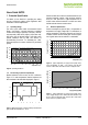
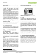
Figure 11 Typical application circuit, including pull-up resistors
R
P
and decoupling of VDD and VSS by a capacitor.
To avoid signal contention the micro-controller unit (MCU)
must only drive SDA and SCL low. External pull-up
resistors (e.g. 10kΩ), are required to pull the signal high.
For the choice of resistor size please take bus capacity
requirements into account (compare Table 5). It should be
noted that pull-up resistors may be included in I/O circuits
of MCUs. See Table 4 and Table 5 for detailed I/O
characteristic of the sensor.
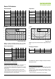
4 Electrical Characteristics
4.1 Absolute Maximum Ratings
The electrical characteristics of SHT2x are defined in
Table 1. The absolute maximum ratings as given in Table
3 are stress ratings only and give additional information.
Functional operation of the device at these conditions is
not implied. Exposure to absolute maximum rating
conditions for extended periods may affect the sensor
reliability (e.g. hot carrier degradation, oxide breakdown).
Parameter
min
max
Units
VDD to VSS
-0.3
5
V
Digital I/O Pins (SDA, SCL)
to VSS
-0.3
VDD + 0.3
V
Input Current on any Pin
-100
100
mA
Table 3 Electrical absolute maximum ratings
ESD immunity is qualified according to JEDEC JESD22-
A114 method (Human Body Model at 4kV), JEDEC
JESD22-A115 method (Machine Model 200V) and ESDA
ESD-STM5.3.1-1999 and AEC-Q100-011 (Charged
Device Model, 750V corner pins, 500V other pins). Latch-
up immunity is provided at a force current of 100mA with
T
amb
= 125°C according to JEDEC JESD78. For exposure
beyond named limits the sensor needs additional
protection circuit.
4.2 Input / Output Characteristics
The electrical characteristics such as power consumption,
low and high level input and output voltages depend on
the supply voltage. For proper communication with the
sensor it is essential to make sure that signal design is
strictly within the limits given in Table 4 & 5 and Figure 12.
Parameter
Conditions
min
typ
max
Units
Output Low
Voltage, VOL
VDD = 3.0 V,
-4 mA < IOL < 0mA
0
-
0.4
V
Output High
Voltage, VOH
70%
VDD
-
VDD
V
Output Sink
Current, IOL
-
-
-4
mA
Input Low
Voltage, VIL
0
-
30%
VDD
V
Input High
Voltage, VIH
70%
VDD
-
VDD
V
Input Current
VDD = 3.6 V,
VIN = 0 V to 3.6 V
-
-
±1
uA
Table 4 DC characteristics of digital input/output pads. VDD =
2.1V to 3.6V, T = -40°C to 125°C, unless otherwise noted.
SDA
SCL
GND
VDD
MCU (master)
R
P
R
P
SCL OUT
SDA OUT
SDA IN
SCL IN
C = 100nF
SHT2x
(slave)
1
6
5
2
4
3