
Data Sheet


Datasheet SHT20
www.sensirion.com Version 3 – December 2011 5/14
recommended to further process the sensors within 1 year
after date of delivery.
It is of great importance to understand that a humidity
sensor is not a normal electronic component and needs to
be handled with care. Chemical vapors at high
concentration in combination with long exposure times
may offset the sensor reading.
For this reason it is recommended to store the sensors in
original packaging including the sealed ESD bag at
following conditions: Temperature shall be in the range of
10°C – 50°C and humidity at 20 – 60%RH (sensors that
are not stored in ESD bags). For sensors that have been
removed from the original packaging we recommend to
store them in ESD bags made of metal-in PE-HD
11
.
In manufacturing and transport the sensors shall be
prevented of high concentration of chemical solvents and
long exposure times. Out-gassing of glues, adhesive tapes
and stickers or out-gassing packaging material such as
bubble foils, foams, etc. shall be avoided. Manufacturing
area shall be well ventilated.
For more detailed information please consult the
document “Handling Instructions” or contact Sensirion.
2.3 Reconditioning Procedure
As stated above extreme conditions or exposure to solvent
vapors may offset the sensor. The following reconditioning
procedure may bring the sensor back to calibration state:
Baking: 100 – 105°C at < 5%RH for 10h
Re-Hydration: 20 – 30°C at ~ 75%RH for 12h
12
.
2.4 Temperature Effects
Relative humidity reading strongly depends on
temperature. Therefore, it is essential to keep humidity
sensors at the same temperature as the air of which the
relative humidity is to be measured. In case of testing or
qualification the reference sensor and test sensor must
show equal temperature to allow for comparing humidity
readings.
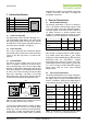
If the sensor shares a PCB with electronic components
that produce heat it should be mounted in a way that
prevents heat transfer or keeps it as low as possible.
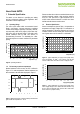
Measures to reduce heat transfer can be ventilation,
reduction of copper layers between the sensor and the
rest of the PCB or milling a slit into the PCB around the
sensor – see Figure 10.
Furthermore, there are self-heating effects in case the
measurement frequency is too high. To keep self heating
below 0.1°C, SHT2x should not be active for more than
11
For example, 3M antistatic bag, product “1910” with zipper.
12
75%RH can conveniently be generated with saturated NaCl solution.
10% of the time – e.g. maximum two measurements per
second at 12bit accuracy shall be made.
Figure 10 Top view of example of mounted SHT2x with slits
milled into PCB to minimize heat transfer.
2.5 Light
The SHT2x is not light sensitive. Prolonged direct
exposure to sunshine or strong UV radiation may age the
sensor.
2.6 Materials Used for Sealing / Mounting
Many materials absorb humidity and will act as a buffer
increasing response times and hysteresis. Materials in the
vicinity of the sensor must therefore be carefully chosen.
Recommended materials are: Any metals, LCP, POM
(Delrin), PTFE (Teflon), PEEK, PP, PB, PPS, PSU, PVDF,
PVF.
For sealing and gluing (use sparingly): Use high filled
epoxy for electronic packaging (e.g. glob top, underfill),
and Silicone. Out-gassing of these materials may also
contaminate the sensor (see Section 2.2). Therefore try to
add the sensor as a last manufacturing step to the
assembly, store the assembly well ventilated after
manufacturing or bake at >50°C for 24h to outgas
contaminants before packing.
2.7 Wiring Considerations and Signal Integrity
Carrying the SCL and SDA signal parallel and in close
proximity (e.g. in wires) for more than 10cm may result in
cross talk and loss of communication. This may be
resolved by routing VDD and/or VSS between the two
SDA signals and/or using shielded cables. Furthermore,
slowing down SCL frequency will possibly improve signal
integrity. Power supply pins (VDD, VSS) must be
decoupled with a 100nF capacitor – see next Section.