
Data Sheet

Datasheet SHT1x
www.sensirion.com Version 4.3 – May 2010 8/11
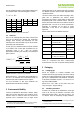
Bit Type Description Default
7 reserved 0
6 R
End of Battery (low voltage
detection)
‘0’ for VDD > 2.47
‘1’ for VDD < 2.47
X
No default value,
bit is only updated
after a
measurement
5 reserved 0
4 reserved 0
3 For Testing only, do not use
0
2 R/W Heater 0 off
1 R/W no reload from OTP 0 reload
0 R/W
’1’ = 8bit RH / 12bit Temp.
resolution
’0’ = 12bit RH / 14bit Temp.
resolution
0
12bit RH
14bit Temp.
Table 5: Status Register Bits
Measurement resolution: The default measurement
resolution of 14bit (temperature) and 12bit (humidity) can
be reduced to 12 and 8bit. This is especially useful in high
speed or extreme low power applications.
End of Battery function detects and notifies VDD voltages
below 2.47V. Accuracy is 0.05V.
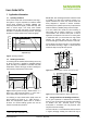
Heater: An on chip heating element can be addressed by
writing a command into status register. The heater may
increase the temperature of the sensor by 5 – 10°C
12
beyond ambient temperature. The heater draws roughly
8mA @ 5V supply voltage.
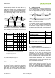
For example the heater can be helpful for functionality
analysis: Humidity and temperature readings before and
after applying the heater are compared. Temperature shall
increase while relative humidity decreases at the same
time. Dew point shall remain the same.
Please note: The temperature reading will display the
temperature of the heated sensor element and not
ambient temperature. Furthermore, the sensor is not
qualified for continuous application of the heater.
OTP reload: With this operation the calibration data is
uploaded to the register before each measurement. This
may be deactivated for reducing measurement time by
about 10ms.
4 Conversion of Signal Output
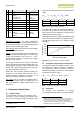
4.1 Relative Humidity
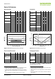
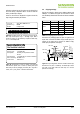
For compensating non-linearity of the humidity sensor –
see Figure 18 – and for obtaining the full accuracy of the
sensor it is recommended to convert the humidity readout
12
Corresponds to 9 – 18°F
(SO
RH
) with the following formula with coefficients given in
Table 6:
2
RH3RH21linear
SOcSOccRH (%RH)
SO
RH
c
1
c
2
c
3
12 bit -2.0468 0.0367 -1.5955E-6
8 bit -2.0468 0.5872 -4.0845E-4
Table 6: V4 humidity conversion coefficients
The values given in Table 6 are optimized coefficients for
V4 sensors. The parameter set for V3 sensors, which has
been proposed in earlier datasheets, still applies and is
provided by Sensirion upon request.
Values higher than 99% RH indicate fully saturated air and
must be processed and displayed as 100%RH
13
. Please
note that the humidity sensor has no significant voltage
dependency.
0%
20%
40%
60%
80%
100%
0 500 1000 1500 2000 2500 3000 3500
SO
RH
sensor readout (12bit)
Relative Humidity
Figure 18: Conversion from SO
RH
to relative humidity
4.2 Temperature compensation of Humidity Signal
For temperatures significantly different from 25°C (~77°F)
the humidity signal requires temperature compensation.
The temperature correction corresponds roughly to
0.12%RH/°C @ 50%RH. Coefficients for the temperature
compensation are given in Table 7.
linearRH21Ctrue
RHSOtt25TRH
SO
RH
t
1
t
2
12 bit 0.01 0.00008
8 bit 0.01 0.00128
Table 7: Temperature compensation coefficients
14
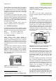
4.3 Temperature
The band-gap PTAT (Proportional To Absolute
Temperature) temperature sensor is very linear by design.
13
If wetted excessively (strong condensation of water on sensor surface),
sensor output signal can drop below 100%RH (even below 0%RH in some
cases), but the sensor will recover completely when water droplets
evaporate. The sensor is not damaged by water immersion or condensation.
14
Coefficients apply both to V3 as well as to V4 sensors.