
Data Sheet

Datasheet SHT1x
www.sensirion.com Version 4.3 – May 2010 7/11
Communication terminates after the acknowledge bit of
the CRC data. If CRC-8 checksum is not used the
controller may terminate the communication after the
measurement data LSB by keeping ACK high. The device
automatically returns to Sleep Mode after measurement
and communication are completed.
Important: To keep self heating below 0.1°C, SHT1x
should not be active for more than 10% of the time – e.g.
maximum one measurement per second at 12bit accuracy
shall be made.
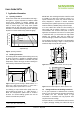
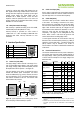
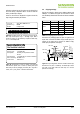
3.4 Connection reset sequence
If communication with the device is lost the following signal
sequence will reset the serial interface: While leaving
DATA high, toggle SCK nine or more times – see Figure
13. This must be followed by a Transmission Start
sequence preceding the next command. This sequence
resets the interface only. The status register preserves its
content.
Figure 13: Connection Reset Sequence
3.5 CRC Checksum calculation
The whole digital transmission is secured by an 8bit
checksum. It ensures that any wrong data can be detected
and eliminated. As described above this is an additional
feature of which may be used or abandoned. Please
consult Application Note “CRC Checksum” for information
on how to calculate the CRC.
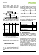
3.6 Status Register
Some of the advanced functions of the SHT1x such as
selecting measurement resolution, end-of-battery notice,
use of OTP reload or using the heater may be activated by
sending a command to the status register. The following
section gives a brief overview of these features.
After the command Status Register Read or Status
Register Write – see Table 4 – the content of 8 bits of the
status register may be read out or written. For the
communication compare Figure 14 and Figure 15 – the
assignation of the bits is displayed in Table 5.
0
0
0
0
0
1
1
0
Status Register
TS
ACK
Bit 7
ACK
Figure 14: Status Register Write
Figure 15: Status Register Read
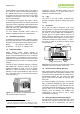
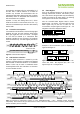
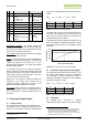
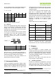
Examples of full communication cycle are displayed in
Figure 16 and Figure 17.
0
0
0
Command 0
0
MSB
TS
Wait for
DATA ready
ACK
LSB Checksum
LSb
ACK
ACK
Figure 16: Overview of Measurement Sequence. TS = Trans-
mission Start, MSB = Most Significant Byte, LSB = Last
Significant Byte, LSb = Last Significant Bit.
Figure 17: Example RH measurement sequence for value “0000’0100“0011’0001” = 1073 = 35.50%RH (without temperature
compensation). DATA valid times are given and referenced in boxes on DATA line. Bold DATA lines are controlled by sensor while plain
lines are controlled by the micro-controller.
0
0
0
0
0
1
1
1
Status Register Checksum
TS
ACK
Bit 7
ACK
Bit 7
ACK
DATA
SCK
8
0%
2
0%
8
0%
2
0%
1
2
3
2
4 - 8
9
Transmission Start
DATA
DATA
SCK
SCK
SCK
DATA
A2
A1
A0
C4
C3 C2 C1
C0 ACK
15 14
13
12 11 10
9
8 ACK 7
6 5
4 3
2 1
0 ACK
7 6
5 4
3
2 1 0
ACK
Transmission Start
Address = ‘000
’
Command = ‘00101
’
12bit Humidity Data
CRC
-
8 Checksum
Transmission Start
Measurement
(80ms for 12bit)
Sleep
(wait for next
measurement)
Idle Bits
Skip ACK to end trans
mission
(if
no CR
C is used)
Sensor pulls DATA line low after
completion of measurement
MSb
LSb
MSb
LSb
15
14
13
12
11
10
9
8
ACK
7
6
5
4
3
2
1
0
A2
A1
A0
C4
C3
C2
C1
C0
ACK
7
6
5
4
3
2
1
0
ACK
ACK