
Data Sheet

Datasheet SHT1x
www.sensirion.com Version 4.3 – May 2010 6/11
Absolute maximum ratings for VDD versus GND are +7V
and -0.3V. Exposure to absolute maximum rating
conditions for extended periods may affect the sensor
reliability (e.g. hot carrier degradation, oxide breakdown).
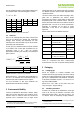
For proper communication with the sensor it is essential to
make sure that signal design is strictly within the limits
given in Table 3 and Figure 11.
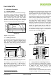
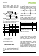
Figure 11: Timing Diagram, abbreviations are explained in
Table 3. Bold DATA line is controlled by the sensor, plain DATA
line is controlled by the micro-controller. Note that DATA valid
read time is triggered by falling edge of anterior toggle.
Parameter Conditions min typ max
Units
VDD > 4.5V
0 0.1 5 MHz
F
SCK
SCK Frequency
VDD < 4.5V
0 0.1 1 MHz
T
SCKx
SCK hi/low time 100
ns
T
R
/T
F
SCK rise/fall time 1 200
* ns
OL = 5pF 3.5 10 20 ns
T
FO
DATA fall time
OL = 100pF
30 40 200
ns
T
RO
DATA rise time ** ** ** ns
T
V
DATA valid time 200
250
*** ns
T
SU
DATA setup time 100
150
*** ns
T
HO
DATA hold time 10 15 **** ns
* T
R_max
+ T
F_max
= (F
SCK
)
-1
– T
SCKH
– T
SCKL
** T
R0
is determined by the R
P
*C
bus
time-constant at DATA line
*** T
V_max
and T
SU_max
depend on external pull-up resistor (R
P
) and total bus
line capacitance (Cbus) at DATA line
**** T
H0_max
< T
V
– max (T
R0
, T
F0
)
Table 3: SHT1x I/O signal characteristics, OL stands for Output
Load, entities are displayed in Figure 11.
3 Communication with Sensor
3.1 Start up Sensor
As a first step the sensor is powered up to chosen supply
voltage VDD. The slew rate during power up shall not fall
below 1V/ms. After power-up the sensor needs 11ms to
get to Sleep State. No commands must be sent before
that time.
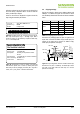
3.2 Sending a Command
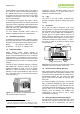
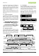
To initiate a transmission, a Transmission Start sequence
has to be issued. It consists of a lowering of the DATA line
while SCK is high, followed by a low pulse on SCK and
raising DATA again while SCK is still high – see Figure 12.
Figure 12: "Transmission Start" sequence
The subsequent command consists of three address bits
(only ‘000’ is supported) and five command bits. The
SHT1x indicates the proper reception of a command by
pulling the DATA pin low (ACK bit) after the falling edge of
the 8th SCK clock. The DATA line is released (and goes
high) after the falling edge of the 9th SCK clock.
Command Code
Reserved 0000x
Measure Temperature 00011
Measure Relative Humidity 00101
Read Status Register 00111
Write Status Register 00110
Reserved 0101x-1110x
Soft reset, resets the interface, clears the
status register to default values. Wait minimum
11 ms before next command
11110
Table 4: SHT1x list of commands
3.3 Measurement of RH and T
After issuing a measurement command (‘00000101’ for
relative humidity, ‘00000011’ for temperature) the
controller has to wait for the measurement to complete.
This takes a maximum of 20/80/320 ms for a 8/12/14bit
measurement. The time varies with the speed of the
internal oscillator and can be lower by up to 30%. To
signal the completion of a measurement, the SHT1x pulls
data line low and enters Idle Mode. The controller must
wait for this Data Ready signal before restarting SCK to
readout the data. Measurement data is stored until
readout, therefore the controller can continue with other
tasks and readout at its convenience.
Two bytes of measurement data and one byte of CRC
checksum (optional) will then be transmitted. The micro
controller must acknowledge each byte by pulling the
DATA line low. All values are MSB first, right justified (e.g.
the 5
th
SCK is MSB for a 12bit value, for a 8bit result the
first byte is not used).
DATA valid
read
DATA valid write
DATA
SCK
8
0%
2
0%
8
0%
2
0%
T
V
T
SCKL
T
SU
T
HO
T
SCK
T
SCKH
T
R
T
F
T
RO
T
FO
DATA
SCK
8
0%
2
0%
8
0%
2
0%