
Data Sheet
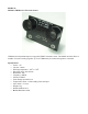
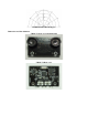
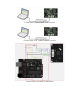

RS485 Interface: Two connectors, + : +5V DC Power +5V - : GND Ground A : A RS485 A(+) B
: B RS485 B(-) ISP Pin:For factory firmware uploading
Communication LED: As the device is powered up, this LED will flash four times which indicates
that the sensor is working properly. This LED will also flash when it is communcating with other
devices. Jumper A:Not in use Jumper B:When the sensor is working under a network, only the
Jumper B for the first Device and the last Device need to be bridged.
Communication Protocols
• The device is fixed at 19200 bps Baud Rate,8/N/1.
• Note:The previous version has 115200 bps Baud Rate,8/N/1.
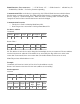
Set Device Address
Command:
Return Value:
PS: The address of each device can be changed when multiple devices are connected. The new Address
must be between 0x11 and 0x80. If the address is set sucessfully, the flag will be set to 0x01 in the
return data. If unsucessful, there is no return data. (The default address for the sensor is 0x12)
Note:The previous default address is 0x11.
Example:
Command: 0x55 0xaa 0x11 0x01 0x55 0x12 0x79 (Set Address to 0x12)
Return: 0x55 0xaa 0x12 0x01 0x55 0x01 0x69 (Address set sucessfully)
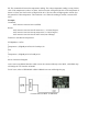
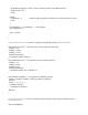
Read tempeature
Command:
Header Address Length Cmd Set Address SUM
55 aa AB 1 55 ADD SUM
Header Address Length Cmd Flag SUM
55 aa ADD 1 55 S SUM
Header Address Length Cmd SUM
55 aa ADD 0 03 SUM
Header Address Length Cmd
High
Byte
Low
Byte
SUM
55 aa ADD 2 03 H L SUM