2/30/2015 4WD Mobile Platform SKU:ROB0022 Robot Wiki 4WD Mobile Platform SKU:ROB0022 Contents [hide] 1 Function Introduction 1.1 STEP1: Assemble Robot 1.2 STEP2: Debug Motor 1.3 STEP3:Install Upper Plate 1.4 STEP4: Debug Ultrasonic Sensor and Servo 1.
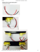
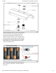
12/30/2015 4WD Mobile Platform SKU:ROB0022 Robot Wiki 2.Soldering the Cables Take the black and red wires out of the parts bag. Attach one black and one red cable (15 cm long) to each motor (4 motors in total). Then use your wire stripper to strip the insulation at both ends of the wires (make sure not to strip too much—refer to the pictures below). Next, solder the wires onto the pins affixed to the motors. Repeat the soldering process for all four motors. https://www.dfrobot.com/wiki/index.
12/30/2015 4WD Mobile Platform SKU:ROB0022 Robot Wiki Note:Pay attention to the correct locations of the red and black wires when soldering. Please consult the following photos for details. 1 2 https://www.dfrobot.com/wiki/index.
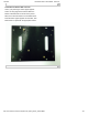
12/30/2015 4WD Mobile Platform SKU:ROB0022 Robot Wiki 3.Assemble the Romeo BLE controller Look in your parts bag for three copper supports. Those 1cmlong supports are used to fasten the Romeo controller board. As shown in the picture below, there are three holes in the controller board. Place the three copper supports into the holes, then fasten them into place with the appropriate screws. https://www.dfrobot.com/wiki/index.
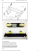
12/30/2015 4WD Mobile Platform SKU:ROB0022 Robot Wiki 4.Assemble the Battery Box Take out two countersunk screws (their heads are flat). Then follow the steps shown in the picture below and affix the battery to the car base. https://www.dfrobot.com/wiki/index.
12/30/2015 4WD Mobile Platform SKU:ROB0022 Robot Wiki 5.Crafting the Power Switch Batteries are the essential lifeblood of robots. To control power usage, we need to use a power switch: the switch turns off power when not in use, thus preserving electricity and battery life. Refer to the picture below before assembling and installing the power switch. Please pay attention to the sequence of the gaskets and screw nuts when assembling the switch. https://www.dfrobot.com/wiki/index.
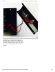
12/30/2015 4WD Mobile Platform SKU:ROB0022 Robot Wiki After assembling the switch, we want to start soldering its wires. Take some of the remaining wire leftover from before. Strip the wiring off both ends of the cables so that the inside of the wire is exposed (same process as with the motors before). We want to solder the exposed end of the wires to the pins on the switch. When soldering, it’s very important that we note the position of the switch’s pins. Let’s do this step by step.
12/30/2015 4WD Mobile Platform SKU:ROB0022 Robot Wiki b)Solder the red cables connecting the switch with the battery charger as shown in the picture below. Here’s another picture to make things clearer. https://www.dfrobot.com/wiki/index.
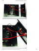
12/30/2015 4WD Mobile Platform SKU:ROB0022 Robot Wiki c)Finally, take one red cable and one black cable. Attach one end of one cable to the negative pole of the battery charger and one end of the other cable to the positive pole of the battery charger. Then attach the other ends of both cables to the Romeo BLE controller. https://www.dfrobot.com/wiki/index.
12/30/2015 4WD Mobile Platform SKU:ROB0022 Robot Wiki https://www.dfrobot.com/wiki/index.
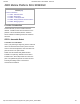
12/30/2015 4WD Mobile Platform SKU:ROB0022 Robot Wiki Looking at this enlarged picture should give you a better idea of how the wires should be connected. After soldering, make sure to check and see if your wiring between the battery and Romeo controller is consistent from start to finish and matches with the above pictures. 6.Assemble the Car Base Using eight M3x6mm screws, attach the side plates to the front and back bumper plates as shown by the diagram below.
/30/2015 4WD Mobile Platform SKU:ROB0022 Robot Wiki This is what the car base should like after it’s been assembled — remember to install the battery pack! 7.Connect the Motors with the Microcontroller Board Now we need to the motors with the microcontroller board. Carefully follow the following diagram: the left motor’s red and black wires should be soldered into M2; the right motor’s red and black wires should be soldered to M1.
12/30/2015 4WD Mobile Platform SKU:ROB0022 Robot Wiki After soldering the motor wires to the microcontroller board, we’re ready to attach the top plate to the base of the car. Before we attach the top plate, you have the option of attaching a sensor plate (see diagram below) — if you don’t plan to use sensors just yet, you can skip this extra step. https://www.dfrobot.com/wiki/index.
12/30/2015 4WD Mobile Platform SKU:ROB0022 Robot Wiki After attaching the top plate, your Pirate should resemble the picture below. 8.Attach an extra level to the Pirate Find the four holes on the base’s top plate. Screw in the four M3x60mm Copper Standoffs, then attach the additional top plate as shown in the diagram below — use M3x6mm screws to affix the plate to the copper standoffs. https://www.dfrobot.com/wiki/index.
12/30/2015 4WD Mobile Platform SKU:ROB0022 Robot Wiki Toss some wheels on your Pirate and you’re ready to let it whip! https://www.dfrobot.com/wiki/index.
12/30/2015 4WD Mobile Platform SKU:ROB0022 Robot Wiki STEP2: Debug Motor Upload the Code int int int int speedPin_M1 = 5; //M1 Speed Control speedPin_M2 = 6; //M2 Speed Control directionPin_M1 = 4; //M1 Direction Control directionPin_M2 = 7; //M1 Direction Control void setup(){ } void loop(){ carAdvance(100,100); delay(1000); carBack(100,100); delay(1000); carTurnLeft(250,250); delay(1000); carTurnRight(250,250); delay(1000); } void carStop(){ // Motor Stop digitalWrite(speedPin_M2,0); digitalWrite(di
12/30/2015 4WD Mobile Platform SKU:ROB0022 Robot Wiki digitalWrite(directionPin_M2,HIGH); } void carTurnRight(int leftSpeed,int rightSpeed){ analogWrite (speedPin_M2,leftSpeed); digitalWrite(directionPin_M1,LOW); analogWrite (speedPin_M1,rightSpeed); digitalWrite(directionPin_M2,LOW); } void carBack(int leftSpeed,int rightSpeed){ analogWrite (speedPin_M2,leftSpeed); digitalWrite(directionPin_M1,LOW); analogWrite (speedPin_M1,rightSpeed); digitalWrite(directionPin_M2,HIGH); } void carAdvance(int leftSpee
12/30/2015 4WD Mobile Platform SKU:ROB0022 Robot Wiki STEP4: Debug Ultrasonic Sensor and Servo 1. Hardware Connection https://www.dfrobot.com/wiki/index.
12/30/2015 4WD Mobile Platform SKU:ROB0022 Robot Wiki 2. Upload Code Download the library firstly.Metro libray #include #include Metro measureDistance = Metro(50); Metro sweepServo = Metro(20); unsigned long actualDistance = 0; Servo myservo; // create servo object to control a servo int pos = 60; int sweepFlag = 1; https://www.dfrobot.com/wiki/index.
12/30/2015 4WD Mobile Platform SKU:ROB0022 Robot Wiki int URPWM = 3; // PWM Output 0-25000US,Every 50US represent 1cm int URTRIG= 10; // PWM trigger pin uint8_t EnPwmCmd[4]={0x44,0x02,0xbb,0x01}; // distance measure command void setup(){ myservo.attach(9); Serial.begin(9600); SensorSetup(); } // Serial initialization // Sets the baud rate to 9600 void loop(){ if(measureDistance.check() == 1){ actualDistance = MeasureDistance(); // Serial.println(actualDistance); // delay(100); } if(sweepServo.
12/30/2015 4WD Mobile Platform SKU:ROB0022 Robot Wiki 3. Adjust the servo position Method 1: Reinstall wheel Method 2: Adapt your code accordingly STEP5: Debugging Robot 1. Fix the expansion board Uplpad the code #include #include
12/30/2015 4WD Mobile Platform SKU:ROB0022 Robot Wiki int URTRIG= 10; // PWM trigger pin uint8_t EnPwmCmd[4]={0x44,0x02,0xbb,0x01}; void setup(){ myservo.attach(9); Serial.begin(9600); SensorSetup(); } // distance measure command // Serial initialization // Sets the baud rate to 9600 void loop(){ if(measureDistance.check() == 1){ actualDistance = MeasureDistance(); // Serial.println(actualDistance); // delay(100); } if(sweepServo.check() == 1){ servoSweep(); } if(actualDistance <= 30){ myservo.
12/30/2015 4WD Mobile Platform SKU:ROB0022 Robot Wiki if(distance==50000){ Serial.print("Invalid"); }else{ distance=distance/50; } return distance; // the reading is invalid.
12/30/2015 4WD Mobile Platform SKU:ROB0022 Robot Wiki Your own car was born! https://www.dfrobot.com/wiki/index.