
Data Sheet

MLX90614 family
Single and Dual Zone
Infra Red Thermometer in TO-39
3901090614 Page 40 of 52 Data Sheet
Rev 008 February 28, 2013
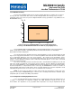
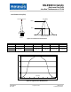
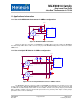
11.3 PWM output operation
Using the PWM output mode of the MLX90614 is very simple, as shown in Figure 37.
J1
CON1
PWM
Vdd
GND
2
0.1uF
Vdd
U1
MLX90614
Vss
PWM
SDA
1
C1
SCL
Vz
3
Figure 37: Connection of MLX90614 for PWM output mode
The PWM mode is free-running after POR when configured in EEPROM. The SCL pin must be forced
high for PWM mode operation (can be shorted to V
DD
pin).
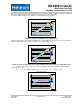
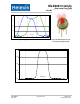
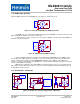
A pull-up resistor can be used to preserve the option for SMBus operation while having PWM as a
default as is shown on Figure 38.
PWM
SDA
10k
3
1
Vdd
2
R1
SCL
Vz
J1
CON1
SCL
PWM/SDA
GND
Vdd
U1
MLX90614
Vss
0.1uF
C1
Figure 38: PWM output with SMBus available
Again, the PWM mode needs to be written as the POR default in EEPROM. Then for PWM operation
the SCL line can be high impedance, forced high, or even not connected. The pull-up resistor R1 will ensure
there is a high level on the SCL pin and the PWM POR default will be active. SMBus is still available (for
example – for further reconfiguration of the MLX90614, or sleep mode power management) as there are pull-up
resistors on the SMBus lines anyway.
PWM can be configured as open drain NMOS or a push-pull output. In the case of open drain external
pull-up will be needed. This allows cheap level conversion to lower logic high voltage. Internal pull-ups present
in many MCUs can also be used.
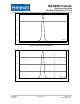
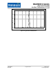
11.4 Thermal alert / thermostat
U2
AC line
R1
3
C2
10uF
C1
0.1uF
U1 MCU
SCL
SDA
GND
Vdd
2
SCL
Vz
C*
2
SCL
Vz
U1
MLX90614Axx
U1
MLX90614Bxx
Vss
Vdd
1 1
SMBus
R2
Vdd
4
Q1
4
1
+5V
U1
MLX90614Axx
Vdd
Vss
+3.3V R1
C3
0.1uF
SCL
Vz
3
R2
+24V
Vss
C1
0.1uF
PW M
SDA
PW M
SDA
3
4
PWM
SDA
D1
Alert dev ice
+
-
2
Figure 39: Thermal alert / thermostat applications of MLX90614