
Data Sheet

MLX90614 family
Single and Dual Zone
Infra Red Thermometer in TO-39
3901090614 Page 22 of 52 Data Sheet
Rev 008 February 28, 2013
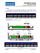
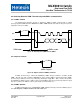
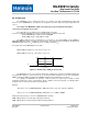
8.5.1 Single PWM format
In single PWM output mode the settings for PWM1 data only are used. The temperature reading can be
calculated from the signal timing as:
MINOMINOMAXOOUT
TTT
T
t
T
___
2
2
where Tmin and Tmax are the corresponding rescale coefficients in EEPROM for the selected temperature
output (Ta, object temperature range is valid for both Tobj1 and Tobj2 as specified in the previous table) and T
is the PWM period. Tout is T
O1
, T
O2
or T
a
according to Config Register [5:4] settings.
The different time intervals t
1
…t
4
have following meaning:
t
1
: Start buffer. During this time the signal is always high. t
1
= 0.125s x T (where T is the PWM period,
please refer to Figure 14).
t
2
: Valid Data Output Band, 0…1/2T. PWM output data resolution is 10 bit.
t
3
: Error band – information for fatal error in EEPROM (double error detected, not correctable).
t
3
= 0.25s x T. Therefore a PWM pulse train with a duty cycle of 0.875 will indicate a fatal error in EEPROM (for
single PWM format). FE means Fatal Error.
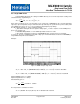
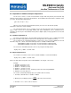
Example:
Figure 15: PWM example single mode
CT
MINO
0
_
3602731515.273100010,
__
ABxdTxEEPROMT
MINOMINO
CT
MAXO
50
_
BExdTxEEPROMT
MAXOMAXO
3703231515.273100000,
__
Captured PWM period is T = 1004s
Captured high duration is t = 392 s
Calculated duty cycle is:
3904.0
1004
392
T
t
D
or
%04.39
The temperature is calculated as follows:
CT
O
54.26502654.020050125.03904.02