
Data Sheet

MLX90614 family
Single and Dual Zone
Infra Red Thermometer in TO-39
3901090614 Page 21 of 52 Data Sheet
Rev 008 February 28, 2013
8.5 PWM
The MLX90614 can be read via PWM or SMBus compatible interface. Selection of PWM output is done
in EEPROM configuration (factory default is SMBus). PWM output has two programmable formats, single and
dual data transmission, providing single wire reading of two temperatures (dual zone object or object and
ambient). The PWM period is derived from the on-chip oscillator and is programmable.
Config Register[5:4] PWM1 data
PWM2 data Tmin,1 Tmax,1 Tmin,2 Tmax,2
00 T
A
T
O1
T
A_range
,L T
A_range
,H T
O_MIN
T
O_MAX
01 T
A
T
O2
T
A_range
,L T
A_range
,H T
O_MIN
T
O_MAX
11 T
O1
T
O2
T
O_MIN
T
O_MAX
T
O_MIN
T
O_MAX
10* T
O2
Undefined T
O_MIN
T
O_MAX
N.A. N.A.
Table 12: PMW configuration table
Note: Serial data functions (2-wire / PWM) are multiplexed with a thermal relay function (described in the
“Thermal relay” section).
* Not recommended for extended PWM format operation
t1 t2
t3
t4
FE
Valid data band
Error band
Start Stop
0
T
5
8
T
1
8
T
13
16
T
7
8
T
t1 t2
t3
t4
FE
Sensor 1
Error band
Start
Stop
0
T
1
16
TT
5
16
T
7
16
T
8
16
Valid data band
t5 t6
Sensor 1
t7
FE
Error band
Sensor 2
Sensor 2
Valid data band
t8
T
9
16
T
13
16
T
15
16
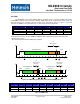
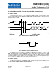
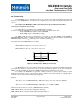
Figure 14: PWM timing single (above) and extended PWM (bellow)
PWM type t1 t2 t3 t4 t5 t6 t7 t8
Single 1/8 – high 4/8 - var 2/8 1/8 – low
NA NA NA NA
Extended - S1 1/16 - high 4/16 - var 2/16 1/16 - low 1/16 - low 4/16 – low 2/16 - low 1/16 - low
Extended - S2 1/16 - high 4/16 - high 2/16 - high 1/16 - high 1/16 - high 4/16 - var 2/16 1/16 - low
Table 13: PMW timing