
Data Sheet

MLX90614 family
Single and Dual Zone
Infra Red Thermometer in TO-39
3901090614 Page 15 of 52 Data Sheet
Rev 008 February 28, 2013
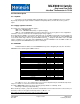
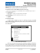
Note*: This address is readable and writable. Bit 3 should not be altered as this will cancel the factory
calibration.
Note**: EEPROM error signaling is implemented in automotive grade parts only.
8.4.2 Differences with the standard SMBus specification (reference [1])
There are eleven command protocols for standard SMBus interface. The MLX90614 supports only two of
them. Not supported commands are:
Quick Command
Byte commands - Sent Byte, Receive Byte, Write Byte and Read Byte
Process Call
Block commands – Block Write and Write-Block Read Process Call
Supported commands are:
Read Word
Write Word
8.4.3 Detailed description
The PWM / SDA pin of MLX90614 can operate also as PWM output, depending on the EEPROM
settings. If PWM is enabled, after POR the PWM / SDA pin is directly configured as PWM output. Even if the
device is in PWM mode SMBus communication may be restored by a special command. That is why hereafter
both modes are treated separately.
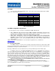
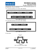
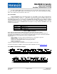
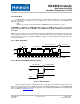
8.4.3.1 Bus Protocol
Figure 4: SMBus packet element key
After every received 8 bits the SD should issue ACK or NACK. When a MD initiates communication, it
first sends the address of the slave and only the SD which recognizes the address will ACK, the rest will remain
silent. In case the SD NACKs one of the bytes, the MD should stop the communication and repeat the
message. A NACK could be received after the PEC. This means that there is an error in the received message
and the MD should try sending the message again. The PEC calculation includes all bits except the START,
S
Wr
Slave Address
A
Data Byte
A
P
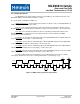
S
Start Condition
Sr
Repeated Start Condition
Rd
Read (bit value of 1)
Wr
Write (bit value of 0)
A
Acknowledge (this bit can be 0 for ACK and 1 for NACK)
S
Stop Condition
PEC
Packet Error Code
Master
-
to
-
Slave
Slave-to-Master
1
1
7
1
8
1
1