
Data Sheet


MP2636 –3.0A SINGLE CELL SW MODE BATTERY CHARGER WITH PPM AND 3.0A BOOST
MP2636 Rev.1.01 www.MonolithicPower.com 37
9/16/2015 MPS Proprietary Information. Patent Protected. Unauthorized Photocopy and Duplication Prohibited.
© 2015 MPS. All Rights Reserved.
Based on equation (18) and equation (19),
R
T1=6.65k and RT2 = 25.63k are suitable for
an NTC window between 0°C and 50°C. Chose
approximate values: e.g., R
T1
=6.65k and
R
T2
=25.5k.
If no external NTC is available, connect R
T1
and
R
T2
to keep the voltage on the NTC pin within the
valid NTC window: e.g., R
T1
= R
T2
= 10k.
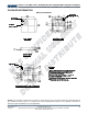
Figure 14: NTC Function Block
For convenience, an NTC thermistor design
spreadsheet is also provided, please inquire if
necessary.
Setting the System Voltage in Boost Mode
In the boost mode, the system voltage can be
regulated to the value customer required
between 4.2V to 6V by the resistor divider at FB
pin as R1 and R2 in the typical application circuit.
SYS
R1 R2
V1.2V
R2
+
=×
(20)
where 1.2V is the voltage reference of SYS. With
a typical value for R2, 10k, R1 can be
determined by:
SYS
V1.2V
R1 R2 ( V )
1.2V
−
=×
(21)
For example, for a 5V system voltage, R2 is
10k, and R1 is 31.6k.
Setting the Output Current Limit in Boost
Mode
In boost mode, connect a resistor from the OLIM
pin to AGND to program the output current limit.
The relationship between the output current limit
and setting resistor is as follows:
OLIM
OLIM
2400 0.92
I(A)
R(k)RS1(m)
×
=
Ω× Ω
(22)
The output current limit of the boost can be
programmed up to 3.0A.
Given a 20m RS1, the expected R
OLIM
for
typical output current limit listed as below:
R
OLIM
(kΩ) Output Current (A)
220.8 1.0
147.2 1.5
110.4 2.0
90.3 2.5
73.6 3.0
Selecting the Inductor
Inductor selection trades off between cost, size,
and efficiency. A lower inductance value
corresponds with smaller size, but results in
higher current ripple, higher magnetic hysteretic
losses, and higher output capacitances. However,
a higher inductance value benefits from lower
ripple current and smaller output filter capacitors,
but results in higher inductor DC resistance (DCR)
loss.
Choose an inductor that does not saturate under
the worst-case load condition.
1. In Charge Mode
When MP2636 works in charge mode (as a Buck
Converter), estimate the required inductance as:
IN BATT BATT
L_MAX IN SW
VV V
L
IVf
−
=×
Δ×
(23)
where V
IN
, V
BATT
, and f
SW
are the typical input
voltage, the CC charge threshold, and the
switching frequency, respectively.
I
L_MAX
is the
maximum peak-to-peak inductor current, which is
usually designed at 30%-40% of the CC charge
current.
With a typical 5V input voltage, 35% inductor
current ripple at the corner point between trickle
charge and CC charge (V
BATT
=3V, I
CHG
=2.5A), the
inductance 2.2H.
2. In Boost Mode
When the MP2636 is in Boost mode (as a Boost
converter), the required inductance value is
calculated as:
BATT SYS BATT
SYS SW L _ MAX
V(VV)
L
Vf I
×−
=
××Δ
(24)
L _ MAX BATT(MAX)
I 30% I
Δ
=×
(25)