
Data Sheet

SD2405ALPI IIC 串行接口的实时时钟IC
!
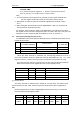
(1) WRITE RTC ENABLE BIT (WRTC1 ,WRTC2,WRTC3):
Registers (00H ~ 1FH) RTC write enable bits. When the three bits are set to “1”,
RTC is enable to be written.
Write enable: Setting the three bits must follow the sequencing: Set the WRTC1 bit to
“1” first, then set the WRTC2 and WRTC3 to “1”.
Write disable: Setting the three bits must follow the sequencing: Set the WRTC2
and WRTC3 bits to “0” first, then set the WRTC1 to “0”.
(2) AUTO RESET ENABLE BIT (ARST): Enables/disables the automatic reset of the
INTAF and INTDF status bits . When ARST bit is set to “1”, these status bits are
reset to “0” after a valid read of the respective status register (with a valid STOP
condition). When the ARST is cleared to “0”, the user must reset the INTAF and
INTDF bits.by your program
(3) FREQUENCY OUTPUT AND INTERRUPT BIT (FOBAT): This bit is used for
enables/disables the INT pin during battery backup mode (i.e. VBAT power
source active). When the FOBAT is set to “1” the INT pin is disabled during battery
backup mode. This means that both the frequency output and alarm output
functions are disabled. When the FOBAT is cleared to “0”, the INT pin is enabled
during battery backup mode.
(4) POWER ON BIT (RTCF): when the dual power( both Vdd add Vbat ) reset,the
RTCF bit will be set to “1” . this bit can be read only.
6. IIC Serial Interface
The SD2405AL supports a bidirectional bus oriented protocol. The protocol defines
any device that sends data onto the bus as a transmitter and the receiving device as the
receiver. The device controlling the transfer is the master and the device being
controlled is the slave. The master always initiates data transfers and provides the clock
for both transmit and receive operations. Therefore, the SD2405AL operates as a slave
device in all applications.
6.1 Protocol Conventions
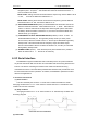
(1) Start
condition
The SCL and SDA pins are at the “H” level when no data transmission is made.
Changing the SDA from “H” to “L” when the SCL and the SDA are “H” activates the start
condition and access is started.
(2) Stop
condition
Changing the SDA from “L” to “H” when the SCL is “H” activates stop condition and
accessing stopped.
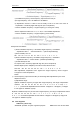
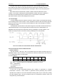
(3) Data valid:
VALID START AND STOP CONDITIONS