
Data Sheet

SD2405ALPI IIC 串行接口的实时时钟IC
!
When one or more of the alarm registers are loaded with a valid second,minute, hour,
day ,week,month,year and its corresponding alarm enable bit is a logic 1, then that
information will be compared with the current second,minute, hour, day ,week,month,year,
When all enabled comparisons first match, the bit INTAF (Alarm flag) is set.
Note:
1. When the week alarm and the date alarm are both enable at the same time, only
the date alarm is valid and the week alarm is invalid.
2. Week alarm register data's format is different from real-time clock week data
format. The bit of Week alarm register
AW6.AW5.AW4.AW3.AW2.AW1.AW0
is
respectively indicated Saturday, Friday, Thursday, Wednesday, Tuesday,
Monday, Sunday. For
example,
AW6, AW1 = 1, and other bits are clear to 0, alarm
interrupt will be output from INT pin on Monday and Saturday.
The INTAF bit will automatically be cleared when the alarm enable register is
written . The alarm interrupt output function is selected by setting the INTS1 bit to
“0”,theINTS0 bit to “1”,
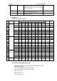
The alarm function can be set in either single event alarm mode or periodic
interrupt alarm mode (seclcted by IM bit).
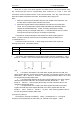
IM
Alarm interrupt mode
INT
0
single event alarm
Remain low until the INTAF bit is reset
1
periodic interrupt alarm
Periodic pulse until the INTAF bit is reset
For exemple:
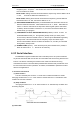
1. Let register 0EH=00000001B, second alarm register 07H=20H, bit INTAE=1、IM=1、
INTS1=0、 INTS0=1. Once second data reaches 20H, INT will generate a 250ms-width
pulse:
2. Let register 0EH=00001111B, week alarm register 0AH=0010 0110B, hour
alarm register 09H=08h, minute alarm register 08H=30h, second alarm register 07H=00h,
Bit INTAE=1、IM=1、INTS1=0、INTS0=1 , when reaching 8:30:00 on Mon, Tue, Fri, INT
Pin will generate a 250ms-width pulse
3. Let register 0EH=00010111B,day alarm register 0BH=01h,hour alarm register
09H=08h,minute alarm 08H=30h, second alarm 07H=00h, Bit INTAE=1 、 IM=1 、
INTS1=0 、 INTS0=1 , when reaching the first day of month at 8:30:00, INT Pin will
generate a 250ms-width pulse
4. Let register 0EH=0111 0100B, year alarm register 0DH=08h,month alarm
register 0CH=08h,day alarm register 0BH=08h, hour alarm register 09H=20h, Bit
INTAE=1 、 IM=0、 INTS1=0 、 INTS0=1、12_/24=1 , when reaching 2008-8-8 20:0:0
INT Pin will generate a 250ms-width pulse
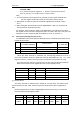
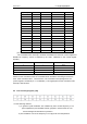
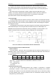
(2) Frequency interrupt
The frequency interrupt is enabled by setting the INTFE bit to “1” .The signal
frequency can be selected by the FS3, FS2, FS1, FS0 bits in the register CTR3: