
Data Sheet

SD2405ALPI IIC 串行接口的实时时钟IC
!
Day of the Week: from 0 to 6.
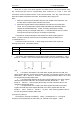
24 HOUR TIME
If 12_/24 bit of the Hour register is “1”, the RTC uses a 24-hour format.
If the 12_/24 bit is “0”, the RTC uses a 12-hour format
Note:
1. You must clear the hour's highest bit 12_/24 after you have gotten the data from
the hour register, otherwise it will be incorrect when the time is P.M.
2. After power on reset, the real time clock data registers aren't cleaned or set to
be "1".
3. When writing the real time data into RTC registers(00H ~ 06H), you must write all
of the total seven bytes data one time .
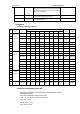
For exemple: when the time is “2006-12-20 Wednesday 18:19:20(24-hour format)”,
the register 00~07H should be Assigned by 20H, 19H, 98H, 03H, 20H, 12H, 06H. The
assignment of hour should be paid more attention, since 12_/24 bit is “1”.
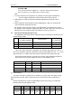
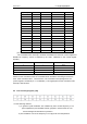
5.3 Interrupt Control Register [08h to 13h]
The SD2405AL have three different interrupts and are controlled by these bits of the
INTAE, INTFE, INTDE :
No.
Interrupt enable bit
(1=enable,0=disable)
Interrupt name
Interrupt flag
(1=Yes,0=No)
1
INTAE
Alarm Interrupt
INTAF
2
INTFE
Frequency Interrupt
--
-
3
INTDE
Countdown timer interrupt
INTDF
When the alarm interrupt is generated, the interrupt flag INTAF bit is set to 1;
when the countdown interrupt is generated, interrupt flag INTDF bit is set to 1; if the
flag bits is set to 1, it need to clear by progarm. Frequency interrupt hasn't any flag.
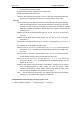
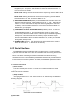
The three interrupts used one output pin INT. The INT output is selected
via INTS0、
INTS1 which are the control register bits of the control register(CTR2).
No.
INTS1
INTS0
Function
0
0
0
Disable output
1
0
1
Alarm Interrupt
2
1
0
Frequency Interrupt
3
1
1
Countdown timer interrupt
(1) Alarm Interrupt
The alarm interrupt is enabled via the INTAE bit, and the alarm time data include
second,minute,hour, day, week, month and year are stored in time alarm registers(07h~
0Dh).
Note:the highest bit of hour alarm register(09h) must be clear to logic "0" all the time.
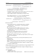
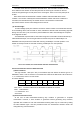
Real time alarm enable register is 0EH:
BIT
D7
D6
D5
D4
D3
D2
D1
D0
Bit name
0
EAY
EAMO
EAD
EAW
EAH
EAMN
EAS
Alarm
enable
-
Year
(0Dh)
Month
(0Ch)
Day
(0Bh)
Week
(0Ah)
Hour
(09h)
Minute
(08h)
Second
(07h)
Note:1=enable ,0=disable.