
Data Sheet


SD2405ALPI IIC 串行接口的实时时钟IC
!
regarded as the “repeated start condition”. Therefore, when 0.5 seconds passed after the
first start condition, access to the SD2405AL is automatically released.
The user shall always be able to access the real-time clock as long as the following two
conditions are met.
1)No stop condition shall be generated until clock read/write is started and completed.
2) One cycle read/write operation shall be completed within 0.5 second.
7. Power Control Operation
The power control circuit accepts a VDD and a VBAT input.
Normal Mode (VDD) to Battery Backup Mode (VBAT)
To transition from the VDD to VBAT mode, the following condition must be met:
V
DD
<
V
BAT
– V
BATHYS
, where V
BATHYS
≈ 100mV
Battery Backup Mode (VBAT) to Normal Mode (VDD)
The SD2405AL device will switch from the VBAT to VDD mode when the following
condition
occurs:
V
DD
> V
BAT
+ V
BATHYS
, where V
BATHYS
≈ 100mV
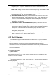
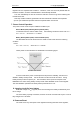
These power control situations are illustrated in the following figure
BATTERY SWITCHOVER
In order to reduce the power consumption and improve the reliability, the I2C bus is
disable in battery backup mode , but the function of internal counter is normal during
battery backup mode. Except the pin SCL and SDA, all the inputs and outputs of the
ISD2405AL are active during battery backup mode unless disabled via the control register.
The User SRAM is operational in battery backup mode down to 1.8V
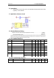
8. charging circuit for inner battery
When the voltage of V
DD
is typical, the circuit will charge the battery automatically until
full of charge.
The inner battery capacity is 5.5mAh, the RTC can work more than half a year. It can be
fully charged over 100 times.
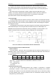
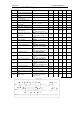
9. Power-on Reset
The reset circus only reset parts of the registers excluding Real time clock registers,