
Data Sheet


Detailed Description
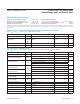
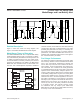
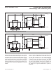
Figure 1 shows the 2-wire bus timing diagram, and
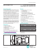
Figure 2 is the MAX17043/MAX17044 block diagram.
ModelGauge Theory of Operation
The MAX17043/MAX17044 use a sophisticated battery
model that determines the SOC of a nonlinear Li+ battery.
The model effectively simulates the internal dynamics of a
Li+ battery and determines the SOC. The model consid-
ers the time effects of a battery caused by the chemical
reactions and impedance in the battery. The MAX17043/
MAX17044 SOC calculation does not accumulate error
with time. This is advantageous compared to traditional
coulomb counters, which suffer from SOC drift caused by
current-sense offset and cell self-discharge. This model
provides good performance for many Li+ chemistry vari-
ants across temperature and age. To achieve optimum
performance, the MAX17043/MAX17044 must be pro-
grammed with configuration data custom to the applica-
tion. Contact the factory for details.
Fuel-Gauge Performance
The classical coulomb-counter-based fuel gauges suffer
from accuracy drift due to the accumulation of the offset
error in the current-sense measurement. Although the
error is often very small, the error increases over time in
such systems, cannot be eliminated, and requires peri-
odic corrections. The corrections are usually performed
on a predefined SOC level near full or empty. Some other
systems use the relaxed battery voltage to perform cor-
rections. These systems determine the true SOC based
on the battery voltage after a long time of no activity. Both
have the same limitation: if the correction condition is not
observed over time in the actual application, the error in
the system is boundless. In some systems, a full-charge/
discharge cycle is required to eliminate the drift error. To
determine the true accuracy of a fuel gauge, as expe-
rienced by end users, the battery should be exercised
in a dynamic manner. The end-user accuracy cannot
be understood with only simple cycles. MAX17043/
MAX17044 do not suffer from the drift problem since they
do not rely on the current information.
Figure 2. Block Diagram
Figure 1. 2-Wire Bus Timing Diagram
STATE
MACHINE
(SOC, RATE)
2-WIRE
INTERFACE
IC
GROUND
TIME BASE
(32kHz)
ADC (V
CELL
)
VOLTAGE
REFERENCE
BIAS
GND
CELL
V
DD
SCL
SDA
ALRT
QSTRT
CTG
MAX17043
MAX17044
SDA
SCL
t
F
t
LOW
t
HD:STA
t
HD:DAT
t
SU:STA
t
SU:STO
t
SU:DAT
t
HD:STA
t
SP
t
R
t
BUF
t
R
t
F
S Sr
P
S
MAX17043/MAX17044 1-Cell/2-Cell Fuel Gauge with
ModelGauge and Low-Battery Alert
www.maximintegrated.com
Maxim Integrated
│
6