
Data Sheet
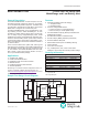
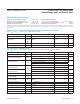

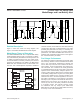
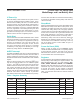
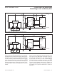

Figure 6 shows an example application for a 1S cell pack.
The MAX17043 is mounted on the system side and pow-
ered directly from the cell pack. The external RC networks
on V
DD
and CELL provide noise filtering of the IC power
supply and A/D measurement. In this example, the ALRT
pin is connected to the microprocessor’s interrupt input
to allow the MAX17043 to signal when the battery is low.
The QSTRT pin is unused in this application, so it is tied
to GND.
Figure 7 shows a MAX17044 example application using
a 2S cell pack. The MAX17044 is mounted on the sys-
tem side and powered from a 3.3V supply generated
by the system. The CELL pin is still connected directly
to PACK+ through an external noise filter. The ALRT
pin is left unconnected because the interrupt feature is
not used in this application. After power is supplied, the
system watchdog generates a low-to-high transition on
the QSTRT pin to signal the MAX17044 to perform a
quick-start.
Figure 6. MAX17043 Application Example with Alert Interrupt
Figure 7. MAX17044 Application Example with Hardware Reset
PACK-
PACK+
PROTECTION IC
(Li+/POLYMER)
SYSTEM GND
SYSTEM V
DD
BATTERY SYSTEM
MAX17043
CELL
EP
1µF
1kΩ
10nF
150Ω
GND
CTG
SCL
SDA
QSTRT
V
DD
ALRT
SYSTEM µP
I
2
C BUS
MASTER
INTERRUPT
INPUT
4.7kΩ
PACK-
PACK+
PROTECTION IC
(Li+/POLYMER)
SYSTEM GND
SYSTEM V
DD
BATTERY SYSTEM
MAX17044
CELL
1µF
1kΩ
GND
CTG SCL
SDA
QSTRT
V
DD
SYSTEM PMIC
SYSTEM µP
I
2
C BUS
MASTER
3.3V OUTPUT
WATCHDOG
ALRT
EP
MAX17043/MAX17044 1-Cell/2-Cell Fuel Gauge with
ModelGauge and Low-Battery Alert
www.maximintegrated.com
Maxim Integrated
│
10