
Data Sheet

7
TP5551
/
TP5552/TP5554
Ultra Low Noise, 3.5MHz, RRIO Zero-Drift O
p
-am
p
s
www.3peakic.com REV1.0
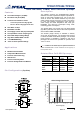
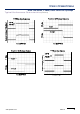
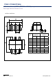
Pin Functions
-IN: Inverting Input of the Amplifier.
+IN: Non-Inverting Input of Amplifier.
OUT: Amplifier Output. The voltage range extends to
within mV of each supply rail.
V+ or +V
s
: Positive Power Supply. Typically the voltage
is from 1.8V to 5.5V. Split supplies are possible as long
as the voltage between V+ and V– is between 1.8V and
5.5V. A bypass capacitor of 0.1F as close to the part as
possible should be used between power supply pins or
between supply pins and ground.
V- or -V
s
: Negative Power Supply. It is normally tied to
ground. It can also be tied to a voltage other than
ground as long as the voltage between V
+
and V
–
is from
1.8V to 5.5V. If it is not connected to ground, bypass it
with a capacitor of 0.1F as close to the part as
possible.
Operation
The TP5551/2/4 op amps are zero drift, rail-to-rail operation amplifiers that can be run from a single-supply voltage.
They use an auto-calibration technique with a time-continuous 3.5MHz op amp in the signal path while consuming only
550A of supply current per channel. This amplifier is zero-corrected with an 150kHz clock. Upon power-up, the
amplifier requires approximately 100s to achieve specified Vos accuracy. This design has no aliasing or flicker noise.
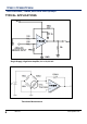
Applications Information
Rail-To-Rail Input And Output
The TP5551/2/4 feature rail-to-rail input and output with a supply voltage from 1.8V to 5.5 V. This allows the amplifier
inputs to have a wide common mode range(50mV beyond supply rails)while maintaining high CMRR(120dB) and
maximizes the signal to noise ratio of the amplifier by having the V
OH
and V
OL
levels be at the V+ and V- rails,
respectively.
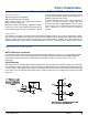
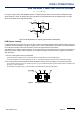
Input Protection
The TP5551/2/4 have internal ESD protection diodes that are connect between the inputs and supply rail. When either
input exceeds one of the supply rails by more than 300mV, the ESD diodes become forward biased and large amounts
of current begin to flow through them. Without current limiting, this excessive fault current causes permanent damage
to the device.
Thus an external series resistor must be used to ensure the input currents never exceed 10mA (see
Figure xx).