
Data Sheet

2
REV1.0 www.3peakic.com
TP5551 / TP5552/TP5554
Ultra Low Noise, 3.5MHz, RRIO Zero-Drift Op-amps
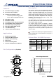
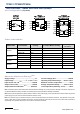
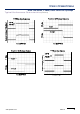
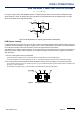
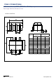
Pin Configuration
(Top View)
Order Information
Model Name Order Number Package Transport Media, Quantity
Marking
Information
TP5551
TP5551-TR SOT23-5
Tape and Reel, 3000
E51T
TP5551-CR SC70-5
Tape and Reel, 3000
51C
TP5551-SR SO-8
Tape and Reel, 4000 TP5551
TP5551U
TP5551U-TR SOT23-5
Tape and Reel, 3000
E51U
TP5551U-CR SC70-5
Tape and Reel, 3000
51V
TP5552
TP5552-SR SO-8 Tape and Reel, 4000 TP5552
TP5552-VR MSOP-8 Tape and Reel, 3000 TP5552
TP5554
TP5554-SR SO-14 Tape and Reel, 2500 TP5554
TP5552-TR TSSOP-14 Tape and Reel, 3000 TP5554
Absolute Maximum Ratings
Note 1
Supply Voltage: .....................................................7V
Input Voltage: ....................... ……V
–
– 0.3 to V
+
+ 0.3
Input Current: +IN, –IN
Note 2
........................... ±20mA
Output Current: OUT...................................... ±60mA
Output Short-Circuit Duration
Note 3
…....... Indefinite
Current at Supply Pins……………............... ±50mA
Operating Temperature Range.......–40°C to 125°C
Maximum Junction Temperature................... 150°C
Storage Temperature Range.......... –65°C to 150°C
Lead Temperature (Soldering, 10 sec) ......... 260°C
Note 1: Stresses beyond those listed under Absolute Maximum Ratings may cause permanent damage to the device. Exposure to
any Absolute Maximum Rating condition for extended periods may affect device reliability and lifetime.
Note 2: The inputs are protected by ESD protection diodes to each power supply. If the input extends more than 500mV beyond the
power supply, the input current should be limited to less than 10mA.
Note 3: A heat sink may be required to keep the junction temperature below the absolute maximum. This depends on the power
supply voltage and how many amplifiers are shorted. Thermal resistance varies with the amount of PC board metal connected to
the package. The specified values are for short traces connected to the leads.