
Product Introduction

1/17/2018 FireBeetle Covers-DC Motor & Stepper Driver SKU:DFR0508 - DFRobot Electronic Product Wiki and Tutorial: Arduino and Robot Wiki-DFRobot…
https://www.dfrobot.com/wiki/index.php/FireBeetle_Covers-DC_Motor_%26_Stepper_Driver_SKU:DFR0508#More 3/12
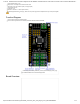
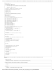
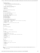
(/wiki/index.php/File:DFR0508_FireBeetle_Covers-DC_Motor%26Stepper_Driver_3.png)
Fig3: DFR0508 FireBeetle Covers-DC Motor&Stepper Driver
STATUS Instruction
LED Mode1: Blink (frequency: 30Hz), indicating the motor drive chip is waiting for initialization commands from the host.
LED Mode2: Lighting, indicating the motor drive chip works well (control motor operation and wait initialization commands from the host).
LED Mode3: OFF, indicating communication error of the motor drive chip.
NOTE: NC means Not Connected, VCC means Output Voltage of power supply (5V-USB;3.7V-lithium battery)
Tutorial
Requirements
Take FireBeetle ESP8266 board (https://www.dfrobot.com/product-1634.html) as an example at here, other Arduino control boards such as arduino UNO
(https://www.dfrobot.com/product-610.html), arduino Mega (https://www.dfrobot.com/product-358.html)… are also can be used.
Hardware
1 x ESP32/ESP8266 Board
1 x FireBeetle Covers-DC Motor&Stepper Driver
1 x Hybrid Stepper Motor for 3D Printer (3.5kg) (https://www.dfrobot.com/product-785.html)
1 x DC Motor
Software
Arduino IDE V1.6.x Click to Download Arduino IDE from Arduino® (https://www.arduino.cc/en/Main/Software)
Please download and install FireBeetle Covers-DC Motor&Stepper Driver library files. (https://github.com/DFRobot/DFRobot_MotorStepper)
About Library installation. (https://www.arduino.cc/en/Guide/Libraries#.UxU8mdzF9H0)
DC Motor Drive
FireBeetle Covers-DC Motor&Stepper Driver can control up to 4-channel DC motors simultaneously. There are 4 marked motor connectors: M1A&M1B, M2A&M2B, M3A&M3B
and M4A&M4B. We’ll show you how to control a DC motor with a Firebeetle or Arduino board.
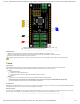
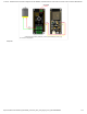
Hardware Connection
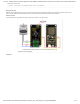
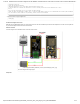
Connect the DC motor to M1A&M1B port, M1A to anode and M1B to cathode. Generally, you need to connect a motor power (4~12V) to Motor PWR port, and connect a logic
power (3.3~5V) to VCC & GND pins. If you use FireBeetle, you can plug the cover on the board, and connect the external power (4~12V).
(/wiki/index.php/File:Warning_yellow.png)