
Data Sheet

© Copyright 2013 WIZnet Co.,Ltd. All rights reserved.
12
iEthernet
W5200
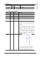
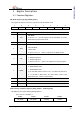
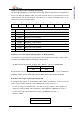
Figure 3 Power Design
Recommend for power design.
1. Locate decoupling capacitor as close as possible to W5200.
2. Use ground plane as wide as possible.
3. If ground plane width is adequate, having a separate analog ground plane and
digital ground plane is good practice.
4. If ground plane is not wide, design analog and digital ground planes as a single
ground plane, rather than separate them.
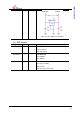
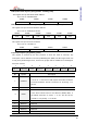
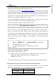
1.5 Clock Signals
Symbol Type Pin No Description
XI I 1 25MHz crystal input/output. A 25MHz crystal and
Oscillator is used to connect these pins.
XO O 2