
Data Sheet

© Copyright 2013 WIZnet Co.,Ltd. All rights reserved.
11
iEthernet
W5200
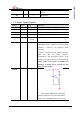
This function activates only during reset
period
RSV I 7 Reserved Pin
Notes: Pull-Up/Down resistor = Typical value are 10KΩ.
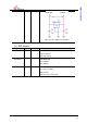
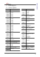
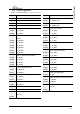
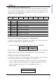
1.4 Power Supply Signals
Symbol Type Pin No Description
VCC3V3A Power 11, 15, 23 3.3V power supply for Analog part
VCC3V3 Power 27, 47 3.3V power supply for Digital part
VCC1V8 Power 8, 25 1.8V power supply for Digital part
GNDA Ground 13, 19, 22, 24
Analog ground
GND Ground 9, 10, 26,
28, 48
Digital ground
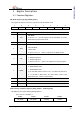
1V8O O 14 1.8V regulator output voltage
1.8V/200mA power created by internal power
regulator, is used for core operation power
( VCC1V8).
Be sure to connect tantalum capacitor between
1V8O and GND for output frequency
compensation, and selectively connect 0.1uF
capacitor for high frequency noise decoupling.
Notice: 1V8O is the power for W5200 core
operation. It should not be connected to the
power of other devices.
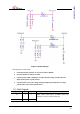
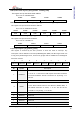
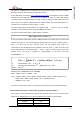
XTALVDD I 16
Figure 2 XTAL_VDD Reference Schematic
Connect a capacitor of 10.1uF to the ground.
※ Refer to the ‘W5200E01-M3 Reference schematic