
Data Sheet

© Copyright 2013 WIZnet Co.,Ltd. All rights reserved.
10
iEthernet
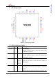
W5200
If you don’t use SPI mode, in other words, if you want to
use indirect mode, then you tied this signal to ‘0’.
This function activate only when reset period.
(*) These pins are related with indirect interface mode. If you need details, Please refer
to the W5200_AN_Indirect.pdf file.
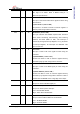
1.2 PHY Signals
Symbol Type Pin No Description
RXIP
I 20 RXIP/RXIN Signal Pair
The differential data from the media is received on
the RXIP/RXIN signal pair.
RXIN
I 21
TXOP O 17 TXOP/TXON Signal Pair
The differential data is transmitted to the media on
the TXOP/TXIN signal pair.
TXON O 18
BIAS O 12 BIAS Register
Connect a resistor of 28.7㏀±1% to the ground.
Refer to the “Reference schematic”.
ANE I 29 Auto Negotiation Mode Enable
This pin selects Enable/Disable of Auto Negotiation
Mode.
Low :Auto Negotiation Mode Disable
High : Auto Negotiation Mode Enable
A0/DUP I 30 Full Duplex Mode Enable
This pin selects Enable/Disable of Full Duplex Mode.
Low = Half Duplex Mode Enable
High = Full Duplex Mode Enable
This function activates only during reset period.
A1/SPD I 31 Speed Mode
This pin selects 100M/10M Speed Mode.
Low = 10M Speed Mode
High = 100M Speed Mode
This function activates only during reset period.
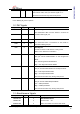
1.3 Miscellaneous Signals
Symbol Type
Pin No Description
FDXLEDn/M2
SPDLEDn/M1
LINKLEDn/M0
I 3,
4,
5
W5200 MODE SELECT
Normal mode : 111
Other test modes are internal test mode.