iEthernet W5200 iEthernet W5200 Datasheet Version 1.3.0 http://www.wiznet.co.kr © Copyright 2013 WIZnet Co.,Ltd. All rights reserved.
iEthernet W5200 W5200 The W5200 chip is a Hardwired TCP/IP embedded Ethernet controller that enables easier internet connection for embedded systems using SPI (Serial Peripheral Interface). W5200 suits best for users who need Internet connectivity for application that uses a single chip to implement TCP/IP Stack, 10/100 Ethernet MAC and PHY. The W5200 is composed of a fully hardwired market-proven TCP/IP stack and an integrated Ethernet MAC & PHY.
iEthernet W5200 Target Applications The W5200 is well suited for many embedded applications, including: - Home Network Devices: Set-Top Boxes, PVRs, Digital Media Adapters - Serial-to-Ethernet: Access Controls, LED displays, Wireless AP relays, etc.
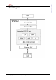
iEthernet W5200 Block Diagram © Copyright 2013 WIZnet Co.,Ltd. All rights reserved.
iEthernet W5200 Table of Contents 1 Pin Assignment............................................................................................ 8 1.1 MCU Interface Signals ....................................................................... 8 1.2 PHY Signals .................................................................................. 10 1.3 Miscellaneous Signals ...................................................................... 10 1.4 Power Supply Signals ...............................
iEthernet W5200 7.4.4 Transformer Characteristics ........................................................ 82 8 IR Reflow Temperature Profile (Lead-Free) ....................................................... 83 9 Package Descriptions .................................................................................. 84 Document History Information ............................................................................ 86 © Copyright 2013 WIZnet Co.,Ltd. All rights reserved.
iEthernet W5200 Table of Figure Figure 1 Pin Description W5200 .................................................................. 8 Figure 2 XTAL_VDD Reference Schematic .................................................... 11 Figure 3 Power Design ........................................................................... 12 Figure 4 Crystal Reference Schematic ........................................................ 13 Figure 5 INTLEVEL Timing ..............................................................
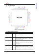
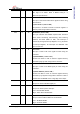
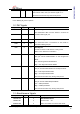
iEthernet W5200 1 Pin Assignment Figure 1 Pin Description W5200 1.1 MCU Interface Signals Symbol Type A0/DUP I Pin No Description (*)ADDRESS[0] 30 This pin is used to select a register or memory when using indirect interface. A1/SPD I (*)ADDRESS[1] 31 This pin is used to select a register or memory when using indirect interface. D7-0 I/O 32, 33, (*)DATA 34, 35, These pins are used to read and write register or 36, 37, memory data.
iEthernet W5200 wait for at least 150ms after high de-assert in order for PLL logic to be stable. Refer to RESET timing of “7 Electrical Specification” CSn I 41 SPI SLAVE SELECT ( Active LOW ) This pin is used to SPI Slave Select signal Pin when using SPI interface. (*)CHIP SELECT ( Active LOW ) Chip Select is for MCU to access to internal registers or memory when using indirect interface.
iEthernet W5200 If you don’t use SPI mode, in other words, if you want to use indirect mode, then you tied this signal to ‘0’. This function activate only when reset period. (*) These pins are related with indirect interface mode. If you need details, Please refer to the W5200_AN_Indirect.pdf file. 1.2 PHY Signals Symbol Type Pin No RXIP I 20 Description RXIP/RXIN Signal Pair The differential data from the media is received on RXIN I 21 the RXIP/RXIN signal pair.
iEthernet W5200 This function activates only during reset period RSV I 7 Notes: Pull-Up/Down resistor = Reserved Pin Typical value are 10KΩ. 1.4 Power Supply Signals Symbol Type Pin No Description VCC3V3A Power 11, 15, 23 3.3V power supply for Analog part VCC3V3 Power 27, 47 3.3V power supply for Digital part VCC1V8 Power 8, 25 1.8V power supply for Digital part GNDA Ground 13, 19, 22, 24 Analog ground GND Ground 9, 10, 26, Digital ground 28, 48 1V8O O 14 1.
iEthernet W5200 Figure 3 Power Design Recommend for power design. 1. Locate decoupling capacitor as close as possible to W5200. 2. Use ground plane as wide as possible. 3. If ground plane width is adequate, having a separate analog ground plane and digital ground plane is good practice. 4. If ground plane is not wide, design analog and digital ground planes as a single ground plane, rather than separate them. 1.5 Clock Signals Symbol Type Pin No XI I 1 Description 25MHz crystal input/output.
_ iEthernet W5200 XTAL OUT XTAL IN Figure 4 Crystal Reference Schematic 1.6 LED Signals Symbol Type Pin No FDXLEDn/M2 O 3 Description Full Duplex/Collision LED Low: Full-duplex High: Half-duplex. SPDLEDn/M1 O 4 Link speed LED Low: 100Mbps High: 10Mbps LINKLEDn/M0 O 5 Link LED Low: Link (10/100M) High: Un-Link blink: TX or RX state on Link © Copyright 2013 WIZnet Co.,Ltd. All rights reserved.
iEthernet W5200 2 Memory Map W5200 is composed of Common Register, Socket Register, TX Memory, and RX Memory as shown below. W5200 Memory Map © Copyright 2013 WIZnet Co.,Ltd. All rights reserved.
iEthernet W5200 3 W5200 Registers 3.
iEthernet W5200 3.
iEthernet W5200 4 Register Descriptions 4.1 Common Registers MR (Mode Register) [R/W] [0x0000] [0x00] This register is used for S/W reset, ping block mode and PPPoE mode. 7 6 RST Bit 5 4 3 WOL PB PPPoE Symbol 2 1 0 Description S/W Reset 7 RST If this bit is ‘1’, internal register will be initialized. It will be automatically cleared after reset. 6 Reserved Reserved Wake on LAN 5 WOL 0:Normal Mode 1:WOL mode If the bit is set as ‘1’, there is waiting for the Magic Packet.
iEthernet W5200 SUBR (Subnet Mask Register) [R/W] [0x0005 – 0x0008] [0x00] This register sets up the subnet mask address. Ex) In case of “255.255.255.0” 0x0005 0x0006 0x0007 0x0008 255 (0xFF) 255 (0xFF) 255 (0xFF) 0 (0x00) SHAR (Source Hardware Address Register) [R/W] [0x0009 – 0x000E] [0x00] This register sets up the Source Hardware address. Ex) In case of “00.08.DC.01.02.
iEthernet W5200 IMR(Interrupt Mask Register)[R/W][0x0016][0x00] The Interrupt Mask Register is used to mask interrupts. Each interrupt mask bit corresponds to a bit in the Interrupt Register2 (IR2). If an interrupt mask bit is set, an interruption will be issued whenever the corresponding bit in the IR2 is set. If any bit in the IMR is set as ‘0’ an interrupt will not occur though the bit.
iEthernet W5200 The timeout of W5200 can be configurable with RTR and RCR. W5200’s timeout has Address Resolution Protocol (ARP) and TCP retransmission timeout. At the ARP (Refer to RFC 826, http://www.ietf.org/rfc.html) retransmission timeout, W5200 automatically sends ARP-request to the peer’s IP address in order to acquire MAC address information (used for communication of IP, UDP, or TCP).
iEthernet W5200 PPPALGO(Authentication Algorithm in PPPoE mode)[R][0x001E][0x00] This register notifies authentication algorithm in PPPoE mode. For detailed information, please refer to PPPoE application note. VERSIONR (W5200 Chip Version Register)[R][0x001F][0x03] This register is the W5200 chip version register. PTIMER (PPP Link Control Protocol Request Timer Register) [R/W] [0x0028] This register indicates the duration for sending LCP Echo Request. Value 1 is about 25ms.
iEthernet W5200 (IR2(S0_IR) = ‘0’). INTn signal becomes High. d. S0_IR is cleared. As IR2 is not 0x00, INTn should be asserted low right after 1PLL_CLK. However, as INTLEVEL is 0x000F, the interrupt about IR is processed after IAWT(16 PLL_CLK). IR2(W5200 SOCKET Interrupt Register)[R/W][0x0034][0x00] IR2 is the Register to notify W5200 SOCKET interrupt to the Host. If any interrupt occurs, the related bit of IR2 is set as ‘1’. When related Mask Bit is ‘1’, INTn signal is asserted low.
iEthernet W5200 PHYSTATUS(W5200 PHY status Register)[R/W][0x0035][0x00] PHYSTATUS is the Register to indicate W5200 status of PHY. Bit Symbol Description 7 Reserved Reserved 6 Reserved Reserved Link Status Register[Read Only] 5 This register indicates Link status.
Reserved Reserved 2 Reserved Reserved 1 Reserved Reserved 0 Reserved Reserved iEthernet W5200 3 4.2 Socket Registers Sn3_MR (Socket n Mode Register) [R/W] [0x4000+0x0n00] [0x00]4 This register sets up socket option or protocol type for each socket. 7 6 5 MULTI MF ND / MC Bit 4 Symbol 3 2 1 0 P3 P2 P1 P0 Description Multicasting 0 : disable Multicasting 1 : enable Multicasting 7 MULTI It is applied only in case of UDP.
0 : using IGMP version 2 1 : using IGMP version 1 This bit is valid when MULTI bit is enabled and UDP mode is used (P3P0 : “0010”).
iEthernet W5200 Sn_CR (Socket n Command Register) [R/W] [0x4001+0x0n00] [0x00] This is used to set the command for Socket n such as OPEN, CLOSE, CONNECT, LISTEN, SEND, and RECEIVE. After W5200 identifies the command, the Sn_CR register is automatically cleared to 0x00. Even though Sn_CR is cleared to 0x00, the command is still being processed. To verify whether the command is completed or not, please check the Sn_IR or Sn_SR registers.
Above three cases, Sn_SR is changed to SOCK_CLOSED. Only valid in TCP mode Regardless of “TCP SERVER” or “TCP CLIENT”, this disconnect command processes the Active close: it transmits disconnect-request(FIN packet) to the connected peer Passive close: When FIN packet is received from peer, a FIN packet is 0x08 DISCON replied back to the peer when FIN/ACK packet is received, Sn_SR is changed to SOCK_CLOSED.
iEthernet W5200 Below commands are only valid for SOCKET 0 and S0_MR(P3:P0) = S0_MR_PPPoE. For more detail refer to the “How to use ADSL”. Value Symbol Description 0x23 PCON 0x24 PDISCON 0x25 PCR In each phase, it transmits REQ message. 0x26 PCN In each phase, it transmits NAK message. 0x27 PCJ In each phase, it transmits REJECT message. PPPoE connection begins by transmitting PPPoE discovery packet Closes PPPoE connection © Copyright 2013 WIZnet Co.,Ltd. All rights reserved.
iEthernet W5200 Sn_IR (Socket n Interrupt Register) [R] [0x4002+0x0n00] [0x00] Sn_IR register provides information such as the type of interrupt (establishment, termination, receiving data, timeout) used in Socket n. When an interrupt occurs and the mask bit of Sn_IMR is ‘1’, the interrupt bit of Sn_IR becomes ‘1’. In order to clear the Sn_IR bit, the host should write the bit as ‘1’. When all the bits of Sn_IR is cleared (‘0’), IR(n) is automatically cleared.
iEthernet W5200 Sn_SR (Socket n Status Register) [R] [0x4003+0x0n00] [0x00] This register provides the status of Socket n . SOCKET status are changed when using the Sn_CR register or during packet transmission/reception. The table below describes the different states of Socket n . Value Symbol 0x00 SOCK_CLOSED Description It is the status that resource of SOCKETn is released.
SOCK_UDP iEthernet W5200 0x22 It is the status that SOCKETn is open as UDP mode. It is changed to SOCK_UDP when Sn_MR(P3:P0) is Sn_MR_UDP and OPEN command is performed. DATA packet can be transferred without connection that is necessary to TCP mode SOCKET. 0x32 SOCK_IPRAW The socket is opened in IPRAW mode. The SOCKET status is change to SOCK_IPRAW when Sn_MR (P3:P0) is Sn_MR_IPRAW and OPEN command is used. IP Packet can be transferred without a connection similar to the UDP mode.
SOCK_LAST_ACK iEthernet W5200 0X1D In case of Passive closing,this status indicate that W5200 waits ACK for FIN packet. It is changed to SOCK_ CLOSED, when Timeout Interrupt occurs (Sn_IR(TIMEOUT)=‘1'). 0x01 SOCK_ARP This status indicates that ARP-request is transmitted in order to acquire destination hardware address. This status is observed when SEND command is performed at the SOCK_UDP or SOCK_IPRAW, or CONNECT command is performed at the SOCK_INIT.
iEthernet W5200 Figure 6 Socket Status Transition Sn_PORT (Socket n Source Port Register) [R/W] [0x4004+0x0n00-0x4005+0x0n00] [0x0000] This register sets the Source Port number for each Socket when using TCP or UDP mode, and the set-up needs to be made before executing the OPEN command.
iEthernet W5200 hardware address that is acquired by ARP-process of CONNECT or SEND command. The host can acquire the destination hardware address through Sn_DHAR after successfully performing CONNET or SEND command. When using PPPoE-process of W5200, PPPoE server hardware address is not required to be set.
iEthernet W5200 At the UDP mode, the destination port number is set in the Sn_DPORT to be used for transmitting UDP DATA packets before performing SEND or SEND_MAC command. At the PPPoE mode, the PPP session ID that is already known is set in the S0_DPORT. PPP session ID (set by S0_DPORT0) is applied to PSIDR after performing the OPEN command.
iEthernet W5200 to online document ( http://www.iana.org/assignments/protocol-numbers ). U U Ex) Internet Control Message Protocol (ICMP) = 0x01, Internet Group Management Protocol = 0x02 Sn_TOS (Socket n IP Type Of Service Register) [R/W] [0x4015+0x0n00] [0x00] It sets the TOS(Type of Service) field of the IP header at the IP layer. It should be set before the OPEN command. Refer to http://www.iana.org/assignments/ip-parameters .
iEthernet W5200 Sn_RXMEM_SIZE(Socket n RX Memory Size Register) [R/W] [0x401E+0x0n00] [0x02] It configures the internal RX Memory size of each SOCKET. RX Memory size of each SOCKET is configurable in the size of 0, 1, 2, 4, 8, and 16 Kbytes. 2Kbytes is assigned when reset. Sn_RXMEM_SIZESUM(sum of Sn_RXMEM_SIZE) of each SOCKET should be 16KB.
iEthernet W5200 Sn_TX_FSR (Socket n TX Free Size Register) [R] [0x4020+0x0n00-0x4021+0x0n00] [0x0800] It notifies the available size of the internal TX memory (the byte size of transmittable data) of Socket n . The host can’t write data as a size bigger than Sn_TX_FSR. Therefore, be sure to check Sn_TX_FSR before transmitting data, and if your data size is smaller than or the same as Sn_TX_FSR, transmit the data with SEND or SEND_MAC command after copying the data.
iEthernet W5200 Figure 7 Physical Address Calculation But this value itself is not the physical address to read. So, the physical address should be calculated as follow. 1. Socket n TX Base Address (hereafter we'll call gSn_TX_BASE) and Socket n TX Mask Address (hereafter we'll call gSn_TX_MASK) are calculated on TMSR value. Refer to the psedo code of the Initialization if detail is needed. 2.
iEthernet W5200 the transmission data to the upper-bound, and change the physical address to the gSn_TX_BASE. Next, write the rest of the transmission data.) After that, be sure to increase the Sn_TX_WR value as much as the data size that indicates the size of writing data. Finally, give SEND command to Sn_CR(Socket n Command Register). Refer to the psedo code of the transmission part on TCP Server mode if detail is needed.
iEthernet W5200 physical address(hereafter, we'll call get_start_address). Sn_RX_WR (Socket n RX Write Pointer Register)[R/W][(0x402A + 0x0n00) – (0x402B + 0x0n00)][0x0000] This register offers the location information to write the receive data. When reading this register, the user should read upper bytes (0x402A, 0x412A, 0x422A, 0x432A, 0x442A, 0x452A, 0x462A, 0x472A) first and lower bytes (0x402B, 0x412B, 0x422B, 0x432B, 0x442B, 0x452B, 0x462B, 0x472B) later to get the correct value.
iEthernet W5200 Sn_FRAG (Socket n Fragment Register)[R/W][0x402D+0x0n00-0x402E+ x0n00][0x4000] It sets the Fragment field of the IP header at the IP layer. W5200 does not support the packet fragment at the IP layer. Even though Sn_FRAG is configured, IP data is not fragmented, and not recommended either. It should be configured before performing OPEN command. Ex) Sn_FRAG0 = 0x4000 (Don’t Fragment) 0x402D 0x402E 0x40 0x00 © Copyright 2013 WIZnet Co.,Ltd. All rights reserved.
iEthernet W5200 5 Functional Descriptions By setting some register and memory operation, W5200 provides internet connectivity. This chapter describes how it can be operated. 5.1 Initialization Basic Setting For the W5200 operation, select and utilize appropriate registers shown below. 1. Mode Register (MR) 2. Interrupt Mask Register (IMR) 3. Retry Time-value Register (RTR) 4. Retry Count Register (RCR) For more information of above registers, refer to the “Register Descriptions.
iEthernet W5200 Set socket memory information This stage sets the socket tx/rx memory information. The base address and mask address of each socket are fixed and saved in this stage.
iEthernet W5200 Figure 8 Allocation Internal TX/RX memory of Socket n © Copyright 2013 WIZnet Co.,Ltd. All rights reserved.
iEthernet W5200 5.2 Data Communications After the initialization process, W5200 can transmit and receive the data with others by ‘open’ the SOCKET of TCP, UDP, IPRAW, and MACRAW mode. The W5200 supports the independently and simultaneously usable 8 SOCKETS. In this section, the communication method for each mode will be introduced. 5.2.1 TCP The TCP is a connection-oriented protocol.
iEthernet W5200 5.2.1.1 TCP SERVER Figure 10 TCP SERVER Operation Flow SOCKET Initialization SOCKET initialization is required for TCP data communication. The initialization is opening the SOCKET. The SOCKET opening process selects one SOCKET from 8 SOCKETS of the W5200, and sets the protocol mode (Sn_MR) and Sn_PORT0 which is source port number (Listen port number in “TCP SERVER”) in the selected SOCKET, and then executes OPEN command.
iEthernet W5200 { START: Sn_MR = 0x01; // sets TCP mode Sn_PORT0 = source_port; // sets source port number Sn_CR = OPEN; // sets OPEN command /* wait until Sn_SR is changed to SOCK_INIT */ if (Sn_SR != SOCK_INIT) Sn_CR = CLOSE; goto START; } LISTEN Run as “TCP SERVER” by LISTEN command.
iEthernet W5200 ESTABLISHMENT : Check received data Confirm the reception of the TCP data. First method : { if (Sn_IR(RECV) == ‘1’) Sn_IR(RECV) = ‘1’; goto Receiving Process stage; /* In this case, if the interrupt of Socket n is activated, interrupt occurs. Refer to IR, IMR Sn_IMR and Sn_IR. */ } Second Method : { if (Sn_RX_RSR0 != 0x0000) goto Receiving Process stage; } The First method: set the Sn_IR(RECV) to ‘1’ whenever you receive a DATA packet.
iEthernet W5200 /* update destination_ptr */ dst_address += upper_size; /* copy left_size bytes of gSn_RX_BASE to destination_address */ left_size = len – upper_size; memcpy(gSn_RX_BASE, dst_address, left_size); } else { copy len bytes of source_ptr to destination_address */ memcpy(src_ptr, dst_ptr, len); } /* increase Sn_RX_RD as length of len */ Sn_RX_RD += len; /* set RECV command */ Sn_CR = RECV; } ESTABLISHMENT: Check send data / Send process The size of the transmit data cannot be larger than assig
iEthernet W5200 { /* first, get the free TX memory size */ FREESIZE: freesize = Sn_TX_FSR; if (freesize (gSn_TX_MASK + 1) ) { /* copy upper_size bytes of source_addr to destination_
iEthernet W5200 ESTABLISHMENT : Check disconnect-request(FIN packet) Check if the Disconnect-request(FIN packet) has been received. User can confirm the reception of FIN packet as below. First method : { if (Sn_IR(DISCON) == ‘1’) Sn_IR(DISCON)=‘1’; goto CLOSED stage; /* In this case, if the interrupt of Socket n is activated, interrupt occurs. Refer to IR, IMR Sn_IMR and Sn_IR.
iEthernet W5200 ESTABLISHMENT: Timeout The timeout can occur by Connect-request(SYN packet) or its response(SYN/ACK packet), the DATA packet or its response(DATA/ACK packet), the Disconnectrequest(FIN packet) or its response(FIN/ACK packet) and transmission all TCP packet. If it cannot transmit the above packets within ‘timeout’ which is configured at RTR and RCR, the TCP final timeout(TCPTO) occurs and the state of Sn_SR is set to SOCK_CLOSED.
iEthernet W5200 5.2.1.2 TCP CLIENT It is same as TCP server except ‘CONNECT’ state. User can refer to the “5.2.1.1 TCP SERVER”. Figure 11 TCP CLIENT Operation Flow CONNECT Transmit the connect-request (SYN packet) to “TCP SERVER”.
iEthernet W5200 5.2.2 UDP The UDP is a Connection-less protocol. It communicates without “connection SOCKET.” The TCP protocol guarantees reliable data communication, but the UDP protocol uses datagram communication which has no guarantees of data communication. Because the UDP does not use “connection SOCKET,” it can communicate with many other devices with the known host IP address and port number.
iEthernet W5200 IP address. At this time, there is no need to get the destination hardware address about destination A, B and C, and also ARPTOis not occurred. Note: Broadcast IP => The Broadcast IP address can be obtained by performing a bit-wise logical OR operation between the bit complement of the subnet mask and the host’s IP address. ex> If IP:”222.98.173.123” and the subnet mask:“255.255.255.0”, broadcast IP is “222.98.173.255” Description Decimal Binary HOST IP 222.098.173.123 11011110.
iEthernet W5200 /* In this case, if the interrupt of Socket n is activated, interrupt occurs. Refer to IR, IMR Sn_IMR and Sn_IR. */ } Second Method : { if (Sn_RX_RSR0 != 0x0000) goto Receiving Process stage; } Receiving process Process the received UDP data in Internal RX memory. The structure of received UDP data is as below. Figure 13 The Received UDP data Format The received UDP data consists of 8bytes PACKET-INFO, and DATA packet.
iEthernet W5200 /* update header_addr*/ header_addr += upper_size; /* copy left_size bytes of gSn_RX_BASE to header_address */ left_size = header_size – upper_size; memcpy(gSn_RX_BASE, header, left_size); /* update src_mask */ src_mask = left_size; } else { /* copy header_size bytes of get_start_address to header_address */ memcpy(src_ptr, header, header_size); /* update src_mask */ src_mask += header_size; } /* update src_ptr */ src_ptr = gSn_RX_BASE + src_mask; /* save remote peer information & received
iEthernet W5200 } /* increase Sn_RX_RD as length of len+ header_size */ Sn_RX_RD = Sn_RX_RD + header_size + get_size; /* set RECV command */ Sn_CR = RECV; } © Copyright 2013 WIZnet Co.,Ltd. All rights reserved.
iEthernet W5200 Check send data / sending process The size of DATA that the user wants to transmit cannot be larger than Internal TX memory. If it is larger than MTU, it is automatically divided by MTU unit and transmitted. The Sn_DIPR0 is set “255.255.255.255” when user wants to broadcast.
iEthernet W5200 /* set SEND command */ Sn_CR = SEND; } Check complete sending / Timeout To transmit the next data, user must check that the prior SEND command is completed. The larger the data size, the more time to complete the SEND command. Therefore, the user must properly divide the data to transmit. The ARPTO can occur when user transmits UDP data. If ARPTO occurs, the UDP data transmission has failed.
iEthernet W5200 5.2.2.2 Multicast The broadcast communication communicates with many and unspecified others. But the multicast communication communicates with many specified others who registered at a multicast-group. Suppose that A, B, and C are registered at a specified multicast-group. If user transmits data to multicast-group (contains A), B and C also receive the DATA for A. To use multicast communication, the destination list registers to multicast-group by using IGMP protocol.
iEthernet W5200 Sn_DHAR3 = 0x01; Sn_DHAR4 = 0x01; Sn_DHAR5 = 0x0B; Sn_DIPR0 = 211; /* set Multicast-Group IP address(211.1.1.
iEthernet W5200 if ( (dst_mask + len) > (gSn_TX_MASK + 1) ) { /* copy upper_size bytes of source_addr to destination_address */ upper_size = (gSn_TX_MASK + 1) – dst_mask; memcpy((0x0000 + source_addr), (0x0000 + dst_ptr), upper_size); /* update source_addr*/ source_addr += upper_size; /* copy left_size bytes of source_addr to gSn_TX_BASE */ left_size = len – upper_size; memcpy( source_addr, gSn_TX_BASE, left_size); } else { /* copy len bytes of source_addr to dst_ptr */ memcpy( source_addr, dst_ptr, len);
iEthernet W5200 5.2.3 IPRAW IPRAW is data communication using TCP, UDP, and IP layers, which are the lower protocol layers. IPRAW supports IP layer protocol such as ICMP (0x01) and IGMP (0x02) according to the protocol number. The ‘ping’ of ICMP or IGMP v1/v2 is already included in W5200 by hardware logic. But if the user needs, the host can directly process the IPRAW by opening the Socket n to IPRAW.
iEthernet W5200 /* sets IP raw mode */ Sn_MR = 0x03; /* sets OPEN command */ Sn_CR = OPEN; /* wait until Sn_SR is changed to SOCK_IPRAW */ if (Sn_SR != SOCK_IPRAW) Sn_CR = CLOSE; goto START; } Check received data Refer to the “5.2.2.1 Unicast & Broadcast.” Receiving process Process the IPRAW data which is received in internal RX memory. The structure of received IPRAW data is as below. Figure 15 The receive IPRAW data Format The IPRAW data consists 6 bytes PACKET-INFO and DATA packet.
iEthernet W5200 5.2.4 MACRAW The MACRAW communication is based on Ethernet MAC, and it can flexibly use upper layer protocol to suit the host’s needs. The MACRAW mode can only be used with a SOCKET. If the user uses the SOCKET in MACRAW mode, not only can it use the SOCKET1~7 in the ‘Hardwired TCP/IP stack’, but it can also be used as a NIC (Network Interface Controller). Therefore, any SOCKET1~7 can be used with ‘Software TCP/IP stack’.
iEthernet W5200 SOCKET Initialization Select the SOCKET and set the SN_MR(P3:P0) to MACRAW mode. Then execute the ‘OPEN’ command. After the ‘OPEN’ command, if the Sn_SR is successfully changed to ‘SOCK_MACRAW’, the SOCKET initialization is completed. Since all information about communication (Source hardware address, Source IP address, Source port number, Destination hardware address, Destination IP address, Destination port number, Protocol header, etc.
iEthernet W5200 src_ptr = gSn_RX_BASE + src_mask; // src_ptr is physical start address /* get the received size */ len = get_Byte_Size_Of_Data_packet // get Byte size of DATA packet from Packet-INFO /* if overflow SOCKET RX memory */ If((src_mask + len) > (gSn_RX_MASK + 1)) { /* copy upper_size bytes of get_start_address to destination_address */ upper_size = (gSn_RX_MASK + 1) – src_mask; memcpy(src_ptr, dst_addr, upper_size); /* update destination_address */ dst_addr += upper_size; /* copy left_size byt
iEthernet W5200 { START: /* sets MAC raw mode with enabling MAC filter */ S0_MR = 0x44; /* sets OPEN command */ S0_CR = OPEN; /* wait until Sn_SR is changed to SOCK_MACRAW */ if (Sn_SR != SOCK_MACRAW) S0_CR = CLOSE; goto START; } ▪If the free size of the internal RX memory is smaller than ‘1528 - Default MTU(1514)+PACKET INFO(2) + DATA packet(8) + CRC(4)’, close the SOCKET and process all received data. Then reopen the SOCKET.
iEthernet W5200 else { /* copy len bytes of src_ptr to destination_address */ memcpy(src_ptr, dst_addr, len); } /* increase Sn_RX_RD as length of len */ Sn_RX_RD += len; /* extract 4 bytes CRC from internal RX memory and then ignore it */ memcpy(src_ptr, dst_addr, len); /* calculate the size of remained data in internal RX memory*/ recved_size = recved_size – 2 – len – 4; } /* Reopen the SOCKET */ /* sets MAC raw mode with enabling MAC filter */ S0_MR = 0x44; /* or S0_MR = 0x04 */ /* sets OPEN command */
iEthernet W5200 dst_ptr = gSn_TX_BASE + dst_mask; // dst_ptr is physical start address /* if overflow SOCKETTX memory */ if ( (dst_mask + len) > (gSn_TX_MASK + 1) ) {/* copy upper_size bytes of source_addr to destination_address */ upper_size = (gSn_TX_MASK + 1) – dst_mask; memcpy(src_ptr, dst_addr, upper_size); /* update source_addr*/ source_addr += upper_size; /* copy left_size bytes of source_addr to gSn_TX_BASE */ left_size = len – upper_size; memcpy(src_ptr, dst_addr, left_size); } else {/* copy len
iEthernet W5200 6 External Interface For the communication with MCU, W5200 provides SPI I/F modes. For the communication with Ethernet PHY, MII is used. 6.1 SPI (Serial Peripheral Interface) mode Serial Peripheral Interface Mode uses only four pins for data communication. Four pins are CSn, SCLK, MOSI, and MISO. Figure 18 SPI Interface 6.2 Device Operations W5200 is controlled by a set of instruction that is sent from a external host , commonly referred to as the SPI Master.
iEthernet W5200 6.3 Process of using general SPI Master device 1. Configure Input/Output direction on SPI Master Device pins. 2. Configure CSn as ‘High’ on inactive 3. Write target address for transmission on SPDR register (SPI Data Register). 4. Write OP code and data length for transmission on SPDR register. 5. Write desired data for transmission on SPDR register. 6. Configure CSn as ‘Low’ (data transfer start) 7. Wait for reception complete 8.
iEthernet W5200 READ Processing The READ Processing Sequence Diagram is shown in Figure 20. The READ processing is entered by driving CSn low, followed by the Address, the OP code, the Data Length and the Dummy data byte on MOSI. And then W5200 read the data byte on MISO. The Address, the OP/Data Length Sequence Diagram and the Data are shown in Figure 19. The OP code (OP) is defined type of the READ OP and WIRTE OP. On OP = 0, the read operation is selected.
iEthernet W5200 CSoff(); // CS=0, SPI start // SpiSendData SpiSendData(((addr+idx) & 0xFF00) >> 8); SpiSendData((addr+idx) & 0x00FF); // Address byte 1 // Address byte 2 // Data write command + Data length upper 7bits SpiSendData((data_read_command| ((data_len& 0x7F00) >> 8))); // Data length bottom 8bits SpiSendData((data_len& 0x00FF)); // Read data:On data_len> 1, Burst Read Processing Mode.
iEthernet W5200 WRITE Processing The WRITE Processing Sequence Diagram is shown in Figure 21.The WRITE processing is entered by driving CSn low, followed by the Address, the OP code, the Data Length, and the Data byte on MOSI. In W5200 SPI mode, the Byte WRITE processing and the Burst WRITE processing are provided. The Byte WRITE processing takes 4 instructions which is consist of the 16-bit Address, the 1-bit OP code(0x1), the 15-bit Data length and 8-bit Data.
iEthernet W5200 CSoff();// CS=0, SPI start SpiSendData(((addr+idx) & 0xFF00) >> 8); SpiSendData((addr+idx) & 0x00FF); // Address byte 1 // Address byte 2 // Data write command + Data length upper 7bits SpiSendData((data_write_command | ((data_len& 0x7F00) >> 8))); // Data length bottom 8bits SpiSendData((data_len& 0x00FF)); // Write data: On data_len> 1, Burst Write Processing Mode.
iEthernet W5200 7 Electrical Specifications 7.1 Absolute Maximum Ratings Symbol Parameter Rating Unit VDD DC Supply voltage -0.5 to 3.63 V VIN DC input voltage -0.5 to 5.5 (5V tolerant) V IIN DC input current ±5 mA TOP Operating temperature -40 to +85 °C TSTG Storage temperature -55 to 125 °C *COMMENT: Stressing the device beyond the “Absolute Maximum Ratings” may cause permanent damage. 7.
iEthernet W5200 7.4 AC Characteristics 7.4.1 Reset Timing Figure 23 Reset Timing Symbol Description Min Max TRC Reset Cycle Time 2 us - TPL RSTn internal PLOCK - 150 ms 7.4.2 Crystal Characteristics Parameter Range Frequency 25 MHz Frequency Tolerance (at 25℃) ±30 ppm Shunt Capacitance 7pF Max Drive Level 59.12uW/MHz Load Capacitance 27pF Aging (at 25℃) ±3ppm / year Max © Copyright 2013 WIZnet Co.,Ltd. All rights reserved.
iEthernet W5200 7.4.3 SPI Timing Figure 24 SPI Timing Symbol 5 Description Min Max Units 80/33.35 MHz FSCK SCK Clock Frequency TWH SCK High Time 6 ns TWL SCK Low Time 6 ns TCS CSn High Time 5 ns TCSS CSn Setup Time 5 TCSH CSn Hold Time 5 ns TDS Data In Setup Time 3 ns TDH Data In Hold Time 3 ns TOV Output Valid Time TOH Output Hold Time TCHZ CSn High to Output Hi-Z - 5 0 ns ns ns 2.
iEthernet W5200 7.4.4 Transformer Characteristics Parameter Transmit End Receive End Turn Ratio 1:1 1:1 Inductance 350 uH 350 uH Figure 25 Transformer Type In case of using internal PHY mode, be sure to use symmetric transformer in order to support Auto MDI/MDIX(Crossover). © Copyright 2013 WIZnet Co.,Ltd. All rights reserved.
iEthernet W5200 8 IR Reflow Temperature Profile (Lead-Free) Moisture Sensitivity Level : 3 Dry Pack Required: Yes Average Ramp-Up Rate 3° C/second max.
iEthernet W5200 9 Package Descriptions Figure 27 Package Dimensions Note: 1. All dimensions are in millimeters. 2. Die thickness allowable is 0.0304 mm MAXMUM (0.012 Inches MAXIMUM) 3. Dimension & tolerances conform to same Y14.5M. -1994. 4. Dimension applies to plated terminal and is measured between 0.20 and 0.25mm from terminal tip. 5. The pin #1 identifier must be placed on the top surface of the package by using indentation mark or other feature of package body. 6.
iEthernet W5200 7. Package warpage max 0.08 mm. 8. Applied for exposed pad and terminals. Exclude embedding part of exposed pad from measuring 9. Applied only to terminals 10. Package corners unless otherwise specified are R0.175+/- 0.025mm © Copyright 2013 WIZnet Co.,Ltd. All rights reserved.
iEthernet W5200 Document History Information Version Date Ver. 1.0.0 Mar2011 Released with W5200 Launching Ver. 1.1.0 13MAR2011 1.Changed “IMR address (0x16 to 0x36)” (P.14, P.18) 2.Changed “IMR2 address (0x36 to 0x16)” (P.14, P.22) Ver. 1.2.0 22APR2011 Descriptions 1. Corrected description of “RSV at 1.3 Miscellaneous Signals” (P.10) 2. Corrected the values of “typical at 7.3 power dissipation” (P.77) 3. Added values of “maximum at 7.3 power dissipation ”(P.77) 4. Removed “PIN31 at 1.
13NOV2012 iEthernet W5200 Ver. 1.2.8 1. Updated description of “W5200”(P.2) 2. Added more information about “indirect interface mode at 1.1 MCU Interface Signals”(P.8) 3. Updated “Figure 1 at 1.1 MCU Interface Signals ”(P.8) corrected Pin6~7, Pin30~39, Pin42~43 4. Updated “pin descriptions at 1.1 MCU Interface Signals”(P.8-13) 5. Updated description of “INTn at 1.1 MCU Interface Signals”(P.9) Added Sn_IR in description 6. Updated “Socket register at 3.2 Socket registers”(P.
8JUL2013 1. iEthernet W5200 Ver.1.3.0 Corrected “PHYSTATUS at 4.1 Common Registers”(P.23) from reserve to Power Save Mode 2. Corrected “IMR at 4.1 Common Registers”(P.19) from Sn_INT to Sn_IMR,n is socket number 3. Added more information about PLL_CLK “INTLEVEL at 4.1 Common Registers”(P.21) 4. Corrected typo for : from IMR to IMR2 in IR at 4.1 Common Registers(P.18) from IR to IR2 in IMR at 4.1 Common Registers(P.19) Copyright Notice Copyright 2013 WIZnet Co.,Ltd. All Rights Reserved.