
Data Sheet


NUC123
May 3, 2017 Page 53 of 99 Rev.2.04
NUC123 SERIES DATASHEET
General Purpose I/O (GPIO) 6.5
6.5.1 Overview
The NuMicro
®
NUC123 series has up to 47 General Purpose I/O pins shared with other function
pins depending on the chip configuration. These 47 pins are arranged in 5 ports named GPIOA,
GPIOB, GPIOC, GPIOD and GPIOF. GPIOA has 6 pins on PA[15:10]. GPIOB has 15 pins on
PB[15:12] and PB[10:0]. GPIOC has 12 pins on PC[13:8] and PC[5:0]. GPIOD has 10 pins on
PD[11:8] and PD[5:0]. GPIOF has 4 pins on PF[3:0]. Each one of the 47 pins is independent and
has the corresponding register bits to control the pin mode function and data.
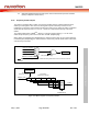
The I/O type of each of I/O pins can be configured by software individually as input, output, open-
drain or quasi-bidirectional mode. After the chip is reset, the I/O mode of all pins are depending
on CIOINI (Config0[10]) (NUC123xxxAEx Only). Each I/O pin has a very weakly individual pull-up
resistor which is about 110 K~300 K for V
DD
is from 5.0 V to 2.5 V.
6.5.2 Features
Four I/O modes:
– Quasi bi-direction
– Push-Pull output
– Open-Drain output
– Input only with high impendence
TTL/Schmitt trigger input selectable by GPx_TYPE[15:0] in GPx_MFP[31:16]
I/O pin can be configured as interrupt source with edge/level setting
Supports High Driver and High Sink I/O mode
Configurable default I/O mode of all pins after reset by CIOINI (Config0[10]) setting
(NUC123xxxAEx Only)
– If CIOINI (Config[10]) is 0, all GPIO pins in input tri-state mode after chip reset
– If CIOINI (Config[10]) is 1, all GPIO pins in Quasi-bidirectional mode after chip reset
I/O pin internal pull-up resistor enabled only in Quasi-bidirectional I/O mode
Enabling the pin interrupt function will also enable the wake-up function