
Data Sheet


NUC123
May 3, 2017 Page 51 of 99 Rev.2.04
NUC123 SERIES DATASHEET
WDT/Timer/PWM Peripherals Clock (when 10 kHz intertnal low speed RC oscillator
(LIRC) is adopted as clock source)
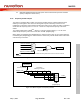
6.3.5 Frequency Divider Output
This device is equipped with a power-of-2 frequency divider which is composed by16 chained
divide-by-2 shift registers. One of the 16 shift register outputs selected by a sixteen to one
multiplexer is reflected to CLKO function pin. Therefore there are 16 options of power-of-2 divided
clocks with the frequency from F
in
/2
1
to F
in
/2
16
where Fin is input clock frequency to the clock
divider.
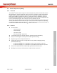
The output formula is F
out
= F
in
/2
(N+1)
, where F
in
is the input clock frequency, F
out
is the clock
divider output frequency and N is the 4-bit value in FSEL (FRQDIV[3:0]).
When writing 1 to DIVIDER_EN (FRQDIV[4]), the chained counter starts to count. When writing 0
to DIVIDER_EN (FRQDIV[4]), the chained counter continuously runs till divided clock reaches low
state and stay in low state.
10
11
00
HCLK
FRQDIV_S (CLKSEL2[3:2])
HIRC (22.1184 MHz)
HXT (4~24 MHz)
FDIV_EN (APBCLK[6])
FRQDIV_CLK
Note: Before clock switching, both the pre-selected and newly selected clock sources must be turned on
and stable.
Figure 6-13 Clock Source of Frequency Divider
0000
0001
1110
1111
:
:
16 to 1
MUX
1/2 1/2
2
1/2
3
1/2
15
1/2
16
…...
FSEL
(FRQDIV[3:0])
CLKO
FRQDIV_CLK
16 chained
divide-by-2 counter
DIVIDER_EN
(FRQDIV[4])
Enable
divide-by-2 counter
Figure 6-14 Block Diagram of Frequency Divider