
Data Sheet


Page | 8
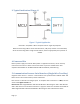
Figure 5 Data "1" Indication
If the response signal from DHT is always at high-voltage-level, it suggests that DHT is not
responding properly and please check the connection. When the last bit data is transmitted,
DHT11 pulls down the voltage level and keeps it for 50us. Then the Single-Bus voltage will be
pulled up by the resistor to set it back to the free status.
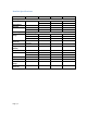
6. Electrical Characteristics
VDD=5V, T = 25℃ (unless otherwise stated)
Note: Sampling period at intervals should be no less than 1 second.
7. Attentions of application
(1) Operating conditions
Applying the DHT11 sensor beyond its working range stated in this datasheet can result in 3%RH
signal shift/discrepancy. The DHT11 sensor can recover to the calibrated status gradually when
it gets back to the normal operating condition and works within its range. Please refer to (3) of
Conditions
Minimum
Typical
Maximum
Power Supply
DC
3V
5V
5.5V
Current
Supply
Measuring
0.5mA
2.5mA
Average
0.2mA
1mA
Standby
100uA
150uA
Sampling
period
Second
1