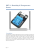
DHT11 Humidity & Temperature Sensor D-Robotics UK (www.droboticsonline.com) DHT11 Temperature & Humidity Sensor features a temperature & humidity sensor complex with a calibrated digital signal output.
DHT 11 Humidity & Temperature Sensor 1. Introduction This DFRobot DHT11 Temperature & Humidity Sensor features a temperature & humidity sensor complex with a calibrated digital signal output. By using the exclusive digital-signal-acquisition technique and temperature & humidity sensing technology, it ensures high reliability and excellent long-term stability.
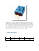
Each DHT11 element is strictly calibrated in the laboratory that is extremely accurate on humidity calibration. The calibration coefficients are stored as programmes in the OTP memory, which are used by the sensor’s internal signal detecting process. The single-wire serial interface makes system integration quick and easy. Its small size, low power consumption and up-to-20 meter signal transmission making it the best choice for various applications, including those most demanding ones.
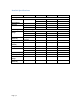
Detailed Specifications: Parameters Humidity Resolution Repeatability Accuracy Conditions Minimum Typical Maximum 1%RH 1%RH 8 Bit ±1%RH ±4%RH 1%RH 25℃ 0-50℃ Interchangeability Fully Interchangeable Measurement 30%RH 0℃ Range 20%RH 25℃ 20%RH 50℃ Response Time 1/e(63%)25℃, 6 S (Seconds) 1m/s Air Hysteresis Long-Term Typical Stability Temperature Resolution 1℃ 8 Bit Repeatability Accuracy ±1℃ Measurement 0℃ Range Response Time 1/e(63%) 6S (Seconds) Page | 4 ±5%RH 10 S 90%RH 90%RH 80%RH 15 S ±1%RH
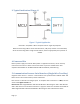
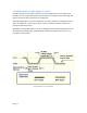
3. Typical Application (Figure 1) Figure 1 Typical Application Note: 3Pin – Null; MCU = Micro-computer Unite or single chip Computer When the connecting cable is shorter than 20 metres, a 5K pull-up resistor is recommended; when the connecting cable is longer than 20 metres, choose a appropriate pull-up resistor as needed. 4. Power and Pin DHT11’s power supply is 3-5.5V DC.
5.1 Overall Communication Process (Figure 2, below) When MCU sends a start signal, DHT11 changes from the low-power-consumption mode to the running-mode, waiting for MCU completing the start signal. Once it is completed, DHT11 sends a response signal of 40-bit data that include the relative humidity and temperature information to MCU. Users can choose to collect (read) some data. Without the start signal from MCU, DHT11 will not give the response signal to MCU.
5.3 DHT Responses to MCU (Figure 3, above) Once DHT detects the start signal, it will send out a low-voltage-level response signal, which lasts 80us. Then the programme of DHT sets Data Single-bus voltage level from low to high and keeps it for 80us for DHT’s preparation for sending data. When DATA Single-Bus is at the low voltage level, this means that DHT is sending the response signal. Once DHT sent out the response signal, it pulls up voltage and keeps it for 80us and prepares for data transmission.
Figure 5 Data "1" Indication If the response signal from DHT is always at high-voltage-level, it suggests that DHT is not responding properly and please check the connection. When the last bit data is transmitted, DHT11 pulls down the voltage level and keeps it for 50us. Then the Single-Bus voltage will be pulled up by the resistor to set it back to the free status. 6. Electrical Characteristics VDD=5V, T = 25℃ (unless otherwise stated) Conditions Minimum Power Supply DC 3V Current Measuring 0.
this section to accelerate its recovery. Please be aware that operating the DHT11 sensor in the non-normal working conditions will accelerate sensor’s aging process. (2) Attention to chemical materials Vapor from chemical materials may interfere with DHT’s sensitive-elements and debase its sensitivity. A high degree of chemical contamination can permanently damage the sensor.