
Manual

15 | P a g e
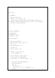
Servo
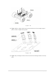
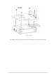
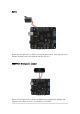
Figure 4-15
Please refer to Figure 4-15 to connect the servo to digital pin 12, the orange line is for
the data, the brown line is for GND, the red line is for Vcc.
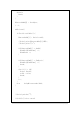
URM37V3.2 Ultrasonic sensor
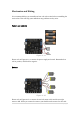
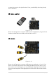
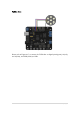
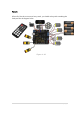
Figure 4-16
Please refer to Figure 4-16 to connect the URM sensor to digital pins 8 (blue), and
13(green), the red line is for 5V+, the black line is for GND.