
Manual

14 | P a g e
to ensure they move in the right direction. If not, you should flip the wiring for only
one of the motors.
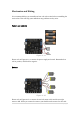
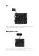
IR remote control
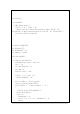
Figure 4-13
Please refer to Figure 4-13 to connect the IR receiver to digital pin 3, the green line is
for data, the black line is for GND, and the red line is for Vcc.
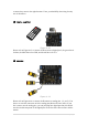
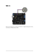
IR sensors
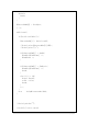
Figure 4-14
Please refer to Figure 4-14 to connect the IR sensors to analog pins 1, 2, and 3. You
have to re-wire the connectors to fit the analog pins (Notice the wire order). If you
don’t want to use the analog pins, you can just plug into digital pins but you should
note that in this setup most of the digital pins are used to drive other sensors and the
motors.