DIY Remote Control Robot Kit (The best Christmas Gift) User Manual v1.0 www.DFRobot.
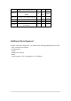
Contents Overall ....................................................................................................................................... 3 Motor Specification ............................................................................................................... 3 Microcontroller...................................................................................................................... 3 Parts List ............................................................................
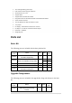
Overall 4WD Mobile platform Motors: 3-12V DC Speed: 90cm/s Dimensions: 200mm x 170mm x 105mm Motor Specification • Gear Ratio 1:120 • No-load speed(3V):100RPM • No-load speed(6V):200RPM • No-load current(3V):60mA • No-load current(6V):71mA • Stall current(3V):260mA • Stall current(6V):470mA • Torque (3V): 1.2Kg/cm • Torque (6V): 1.92Kg/cm • Size: 55mm x 48.
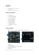
Auto sensing/switching power input ICSP header for direct program download Serial Interface TTL Level Support AREF Support Male and Female Pin Header Integrated sockets for APC220 RF Module and DF-Bluetooth Module Six I2C Interface Pin Sets Two way Motor Driver with 2A maximum current 7 key inputs DC Supply:USB Powered or External 7V~12V DC DC Output:5V /3.
SEN0001 URM37 V3.
Project Ideas The basic robot is intended for you to create a small autonomous or remote controlled robot. Although the kit includes all essential parts to make an autonomous robot, it is intended to allow you to add your own electronics in order to satisfy your objectives. Bluetooth Remote Control We have created some sample code so that you can use your mobile phone with the Bluetooth to control the robot.
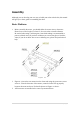
Assembly Although you can develop your own way to build your robot with the kit, this manual will give you a basic guide to assembling the robot. Basic Platform 1. Before assembly the motor, you should solder the motor wires to the motor. Please leave a wire length of at least 15-20 cm in order to install to Romeo. Be careful when using a soldering iron, heat shrink tubing is recommended to protect soldered wires.
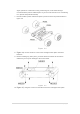
Figure 4-2 4. Figure 4-2; the battery holder is installed with countersunk screws on the fuselage’s lower plate.(tips: you may alternatively use the 7.4V Lipo 2200mAh Battery(FIT0137) at www.DFRobot.com to replace the battery holder). 5. The battery holder uses five AA batteries. You can use 1.2v rechargeable, or 1.5v alkaline batteries. We recommend using rechargeable batteries. Figure 4-3 6. Figure 4-3; before assembly the power switch and power jack, you should solder the wires to the switch and jack.
Again, please be careful when using a soldering iron, heat shrink tubing is recommended to protect soldered parts. If you do not know how to use a soldering iron, please find professional help. 7. Please install the power switch and power jack on the bezel as pictured above in figure 4-3. Figure 4-4 8. Figure 4-4; use the screws to connect the fuselage’s lower plate and motor brackets. 9. Before installing any other parts, you must attach the wheels to the motors.
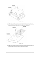
Figure 4-6 11. Figure 4-6; use flange screws to fix the fuselage’s upper plate to the side truss. 12. When installing the fuselage upper plate, make sure the battery cables have been identified and pull the leads out so you can wire them to the Romeo. Figure 4-7 13. Figure 4-7; use flange screws to fix the sensor mounting grill to the bracket. This grill is an option to use if you have any other sensors to install.
Figure 4-8 14. Figure 4-8; the copper stand-offs need to be mounted on the fuselage’s upper plate in order to support the top plate. Figure 4-9 15. Figure 4-9; use flange screws to fix the IR sensor’s mounting bracket on the top plate.
Figure 4-10 16. Figure 4-10; use flange screws to fix the top plate on to the Copper stand-offs.
Electronics and Wiring It is recommended that you assemble and test each sub-section before assembling the entire robot. This will help you troubleshoot any problems as they arise. Power and switch Figure 4-11 Please refer to Figure 4-11 to connect the power supply and switch. Remember that red for positive, and black for negative. Motors Figure 4-12 Please refer to Figure 4-12 to connect the two left motor to M1 and the two right motor to M2.
to ensure they move in the right direction. If not, you should flip the wiring for only one of the motors. IR remote control Figure 4-13 Please refer to Figure 4-13 to connect the IR receiver to digital pin 3, the green line is for data, the black line is for GND, and the red line is for Vcc. IR sensors Figure 4-14 Please refer to Figure 4-14 to connect the IR sensors to analog pins 1, 2, and 3. You have to re-wire the connectors to fit the analog pins (Notice the wire order).
Servo Figure 4-15 Please refer to Figure 4-15 to connect the servo to digital pin 12, the orange line is for the data, the brown line is for GND, the red line is for Vcc. URM37V3.2 Ultrasonic sensor Figure 4-16 Please refer to Figure 4-16 to connect the URM sensor to digital pins 8 (blue), and 13(green), the red line is for 5V+, the black line is for GND.
7LEDs disc Figure 4-17 Please refer to Figure 4-17 to connect the 7LEDs disc to digital pins 9(green), 10(red), and 11(blue), and GND (black) to GND.
Totals When all of the sub-section tests have passed, you should end up with something that looks just like the diagram below.
Support Tech support: techsupport@dfrobot.com Customer Service: sales@dfrobot.com Arduino Code The following demo code is compiled in the Arduino IDE (www.arduino.cc) and uses two subroutines. You are free to copy/paste the code into the Arduino compiler. Ensure the motor controller is connected properly before use. Bluetooth Remote Control //This code is just for Cellbots in android market. #include //version 0.
} void loop(){ AttachCmd(); if(MotorGap.check()){ if(left != 0 || right != 0) Motor_Control(rr,map(constrain(abs(right),10,45), 10, 45,150,255),lr,map(constrain(abs(left),10,45), 10, 45,150,255)); else Motor_Control(0,0,0,0); } } int int int int BluetoothCmd[15]; BlankPos[5]; BlankCount = 0; Endbyte = 0x0A; void AttachCmd(){ if(Serial.
default: break; } } BluetoothCmd[0] = firstByte; i = 1; while(true){ if(Serial.available()){ BluetoothCmd[i] = Serial.read(); //Serial.print(BluetoothCmd[i],HEX); //Serial.print("\t"); if(BluetoothCmd[i] == 0x20){ BlankPos[BlankCount] = i; BlankCount ++; } if(BluetoothCmd[i] == Endbyte){ BlankPos[BlankCount] = i; break; } else if(i >= 14){ Serial.flush(); valid = false; break; } i++; } else delayMicroseconds(100); } //Serial.
if(BluetoothCmd[0] == 's' && BluetoothCmd[1] == 0x0A){ lr = 0; rr = 0; left = 0; right = 0; } if(BluetoothCmd[0] == 'f' && BluetoothCmd[1] == 0x0A){ lr = 0; rr = 0; left = 240; right = 240; } if(BluetoothCmd[0] == 'b' && BluetoothCmd[1] == 0x0A){ lr = 1; rr = 1; left = 240; right = 240; } if(BluetoothCmd[0] == 'l' && BluetoothCmd[1] == 0x0A){ lr = 0; rr = 1; left = 240; right = 240; } if(BluetoothCmd[0] == 'r' && BluetoothCmd[1] == 0x0A){ lr = 1; rr = 0; left = 240; right = 240; } //voice control end if(Blu
char cmd[BlankPos[1] - BlankPos[0]]; for(int j = 0; j < (BlankPos[1] - BlankPos[0]) ; j++){ cmd[j] = BluetoothCmd[j + 1 + BlankPos[0]]; } char Scmd[BlankPos[2] - BlankPos[1]]; for(int j = 0; j < (BlankPos[2] - BlankPos[1]) ; j++){ Scmd[j] = BluetoothCmd[j + 1 + BlankPos[1]]; } Serial.print("cmd:\t"); Serial.print(atoi(cmd)); Serial.print("\t"); Serial.println(atoi(Scmd)); /* */ left = atoi(cmd); right = atoi(Scmd); if(left < 0) lr = 1; else lr = 0; if(right < 0) else rr = 0; rr = 1; } } else Serial.
analogWrite (EN1, LOW); // set low, miniQ stop else analogWrite (EN1, M1_EN); // Otherwise, set the corresponding value /////////// M2 ////////////////////// if (M2_DIR == FORW) // M2 motor direction digitalWrite (IN2, FORW); // set high, the direction of forward else digitalWrite (IN2, BACK); // set low, the direction of backward if (M2_EN == 0) // M2 motor speed analogWrite (EN2, LOW); // set low, to stop else analogWrite (EN2, M2_EN); // set the value for a given } IR Remote Control /* 4WD kit author:La
/* * IRremote: IRrecvDemo - demonstrates receiving IR codes with IRrecv * An IR detector/demodulator must be connected to the input RECV_PIN. * Version 0.1 July, 2009 * Copyright 2009 Ken Shirriff * http://arcfn.com */ #include
void turn_R (char a,char b) { analogWrite (E1,a); digitalWrite(M1,HIGH); analogWrite (E2,b); digitalWrite(M2,LOW); } //Turn Right void setup() { unsigned char i; for (i = 4; i <= 7; i ++) // settings control two of the four pins for the output motor pinMode (i, OUTPUT); Serial.begin(57600); irrecv.enableIRIn(); // Start the receiver } void loop() { if (irrecv.decode(&results)) { Serial.println(results.value, HEX); irrecv.resume(); // Receive the next value } if(output.check()){ switch(results.
case 0xFD20DF: Serial.println("left"); turn_L (240,200); break; case 0xFD609F: Serial.
} void back_off (char a,char b) { analogWrite (E1,a); digitalWrite(M1,LOW); analogWrite (E2,b); digitalWrite(M2,LOW); } void turn_L (char a,char b) { analogWrite (E1,a); digitalWrite(M1,LOW); analogWrite (E2,b); digitalWrite(M2,HIGH); } void turn_R (char a,char b) { analogWrite (E1,a); digitalWrite(M1,HIGH); analogWrite (E2,b); digitalWrite(M2,LOW); } //Move backward //Turn Left //Turn Right void setup() { Serial.
delay(1000); Serial.print( "back" ); Serial.println(""); if (random( 1024 )>512) { turn_R(240,240); delay(1000); Serial.print( "random right" ); Serial.println(""); } else { turn_L(240,240); delay(1000); Serial.print( "random left" ); Serial.println(""); } } else { if (( !( digitalRead( A3) ) || ( !( digitalRead( A2) ) && !( digitalRead( A3) ) ) ))//read sensor from IR distence switch { back_off(240,240); delay(1000); turn_L(240,240); delay(1000); Serial.print( "back and left" ); Serial.
} else { advance(240,240); delay(1000); Serial.print( "go" ); Serial.println(""); } } } } Standard PWM DC control int int int int E1 E2 M1 M2 = = = = 5; 6; 4; 7; //M1 Speed Control //M2 Speed Control //M1 Direction Control //M1 Direction Control ///For previous Romeo, please use these pins.
analogWrite (E1,a); digitalWrite(M1,LOW); analogWrite (E2,b); digitalWrite(M2,LOW); } void turn_L (char a,char b) //Turn Left { analogWrite (E1,a); digitalWrite(M1,LOW); analogWrite (E2,b); digitalWrite(M2,HIGH); } void turn_R (char a,char b) //Turn Right { analogWrite (E1,a); digitalWrite(M1,HIGH); analogWrite (E2,b); digitalWrite(M2,LOW); } void setup(void) { int i; for(i=6;i<=9;i++) pinMode(i, OUTPUT); Serial.begin(19200); //Set Baud Rate } void loop(void) { char val = Serial.
break; } delay(40); } else stop(); } 31 | P a g e
Release Date Dec 7 Version 1.