
Data Sheet

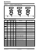
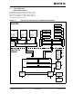
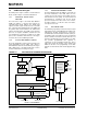
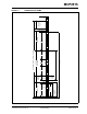
Table Of Contents
- 1.0 Device Overview
- 2.0 Can Message Frames
- 3.0 Message Transmission
- 4.0 Message Reception
- 5.0 Bit Timing
- 6.0 Error Detection
- 7.0 Interrupts
- 8.0 Oscillator
- 9.0 RESET
- 10.0 Modes of Operation
- 11.0 Register Map
- 12.0 SPI™ Interface
- 12.1 Overview
- 12.2 Reset Instruction
- 12.3 Read Instruction
- 12.4 Read RX Buffer Instruction
- 12.5 Write Instruction
- 12.6 Load TX Buffer Instruction
- 12.7 Request-To-Send (RTS) Instruction
- 12.8 Read Status Instruction
- 12.9 RX Status Instruction
- 12.10 Bit Modify Instruction
- Figure 12-1: Bit Modify
- Table 12-1: SPI™ Instruction Set
- Figure 12-2: Read instruction
- Figure 12-3: Read RX Buffer Instruction
- Figure 12-4: Byte Write instruction
- Figure 12-5: Load TX Buffer
- Figure 12-6: Request-to-send (RTS) instruction
- Figure 12-7: BIT Modify instruction
- Figure 12-8: Read Status instruction
- Figure 12-9: RX StatUs Instruction
- Figure 12-10: SPI™ Input Timing
- Figure 12-11: SPI™ Output TIming
- 13.0 Electrical Characteristics
- 14.0 PackAging Information

© 2005 Microchip Technology Inc. Preliminary DS21801D-page 7
MCP2515
2.0 CAN MESSAGE FRAMES
The MCP2515 supports standard data frames,
extended data frames and remote frames (standard
and extended), as defined in the CAN 2.0B
specification.
2.1 Standard Data Frame
The CAN standard data frame is shown in Figure 2-1.
As with all other frames, the frame begins with a Start-
Of-Frame (SOF) bit, which is of the dominant state and
allows hard synchronization of all nodes.
The SOF is followed by the arbitration field, consisting
of 12 bits: the 11-bit identifier and the Remote
Transmission Request (RTR) bit. The RTR bit is used
to distinguish a data frame (RTR bit dominant) from a
remote frame (RTR bit recessive).
Following the arbitration field is the control field,
consisting of six bits. The first bit of this field is the
Identifier Extension (IDE) bit, which must be dominant
to specify a standard frame. The following bit, Reserved
Bit Zero (RB0), is reserved and is defined as a dominant
bit by the CAN protocol. The remaining four bits of the
control field are the Data Length Code (DLC), which
specifies the number of bytes of data (0 – 8 bytes)
contained in the message.
After the control field is the data field, which contains
any data bytes that are being sent, and is of the length
defined by the DLC (0 – 8 bytes).
The Cyclic Redundancy Check (CRC) field follows the
data field and is used to detect transmission errors. The
CRC field consists of a 15-bit CRC sequence, followed
by the recessive CRC Delimiter bit.
The final field is the two-bit Acknowledge (ACK) field.
During the ACK Slot bit, the transmitting node sends
out a recessive bit. Any node that has received an
error-free frame acknowledges the correct reception of
the frame by sending back a dominant bit (regardless
of whether the node is configured to accept that
specific message or not). The recessive acknowledge
delimiter completes the acknowledge field and may not
be overwritten by a dominant bit.
2.2 Extended Data Frame
In the extended CAN data frame, shown in Figure 2-2,
the SOF bit is followed by the arbitration field, which
consists of 32 bits. The first 11 bits are the Most
Significant bits (MSb) (Base-lD) of the 29-bit identifier.
These 11 bits are followed by the Substitute Remote
Request (SRR) bit, which is defined to be recessive.
The SRR bit is followed by the lDE bit, which is
recessive to denote an extended CAN frame.
It should be noted that if arbitration remains unresolved
after transmission of the first 11 bits of the identifier,
and one of the nodes involved in the arbitration is
sending a standard CAN frame (11-bit identifier), the
standard CAN frame will win arbitration due to the
assertion of a dominant lDE bit. Also, the SRR bit in an
extended CAN frame must be recessive to allow the
assertion of a dominant RTR bit by a node that is
sending a standard CAN remote frame.
The SRR and lDE bits are followed by the remaining
18 bits of the identifier (Extended lD) and the remote
transmission request bit.
To enable standard and extended frames to be sent
across a shared network, the 29-bit extended message
identifier is split into 11-bit (most significant) and 18-bit
(least significant) sections. This split ensures that the
lDE bit can remain at the same bit position in both the
standard and extended frames.
Following the arbitration field is the six-bit control field.
The first two bits of this field are reserved and must be
dominant. The remaining four bits of the control field
are the DLC, which specifies the number of data bytes
contained in the message.
The remaining portion of the frame (data field, CRC
field, acknowledge field, end-of-frame and intermis-
sion) is constructed in the same way as a standard data
frame (see Section 2.1 “Standard Data Frame”).
2.3 Remote Frame
Normally, data transmission is performed on an
autonomous basis by the data source node (e.g., a
sensor sending out a data frame). It is possible,
however, for a destination node to request data from
the source. To accomplish this, the destination node
sends a remote frame with an identifier that matches
the identifier of the required data frame. The
appropriate data source node will then send a data
frame in response to the remote frame request.
There are two differences between a remote frame
(shown in Figure 2-3) and a data frame. First, the RTR
bit is at the recessive state and, second, there is no
data field. In the event of a data frame and a remote
frame with the same identifier being transmitted at the
same time, the data frame wins arbitration due to the
dominant RTR bit following the identifier. In this way,
the node that transmitted the remote frame receives
the desired data immediately.
2.4 Error Frame
An error frame is generated by any node that detects a
bus error. An error frame, shown in Figure 2-4, consists
of two fields: an error flag field followed by an error
delimiter field. There are two types of error flag fields.
The type of error flag field sent depends upon the error
status of the node that detects and generates the error
flag field.