
Data Sheet

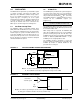
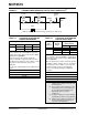
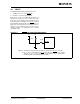

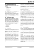

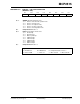

Table Of Contents
- 1.0 Device Overview
- 2.0 Can Message Frames
- 3.0 Message Transmission
- 4.0 Message Reception
- 5.0 Bit Timing
- 6.0 Error Detection
- 7.0 Interrupts
- 8.0 Oscillator
- 9.0 RESET
- 10.0 Modes of Operation
- 11.0 Register Map
- 12.0 SPI™ Interface
- 12.1 Overview
- 12.2 Reset Instruction
- 12.3 Read Instruction
- 12.4 Read RX Buffer Instruction
- 12.5 Write Instruction
- 12.6 Load TX Buffer Instruction
- 12.7 Request-To-Send (RTS) Instruction
- 12.8 Read Status Instruction
- 12.9 RX Status Instruction
- 12.10 Bit Modify Instruction
- Figure 12-1: Bit Modify
- Table 12-1: SPI™ Instruction Set
- Figure 12-2: Read instruction
- Figure 12-3: Read RX Buffer Instruction
- Figure 12-4: Byte Write instruction
- Figure 12-5: Load TX Buffer
- Figure 12-6: Request-to-send (RTS) instruction
- Figure 12-7: BIT Modify instruction
- Figure 12-8: Read Status instruction
- Figure 12-9: RX StatUs Instruction
- Figure 12-10: SPI™ Input Timing
- Figure 12-11: SPI™ Output TIming
- 13.0 Electrical Characteristics
- 14.0 PackAging Information
MCP2515
DS21801D-page 54 Preliminary © 2005 Microchip Technology Inc.
FIGURE 8-3: EXTERNAL SERIES RESONANT CRYSTAL OSCILLATOR CIRCUIT
(1)
TABLE 8-1: CAPACITOR SELECTION FOR
CERAMIC RESONATORS
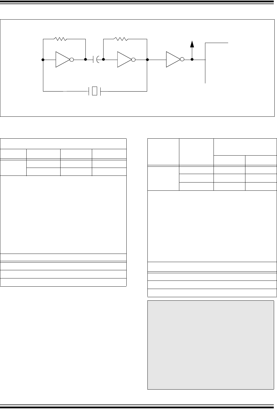
TABLE 8-2: CAPACITOR SELECTION FOR
CRYSTAL OSCILLATOR
330 kΩ
74AS04 74AS04
MCP2510
OSC1
To Other
Devices
XTAL
330 kΩ
74AS04
0.1 mF
Note 1: Duty cycle restrictions must be observed (see Table 12-2).
Typical Capacitor Values Used:
Mode Freq. OSC1 OSC2
HS 8.0 MHz 27 pF 27 pF
16.0 MHz 22 pF 22 pF
Capacitor values are for design guidance only:
These capacitors were tested with the resonators
listed below for basic start-up and operation. These
values are not optimized.
Different capacitor values may be required to
produce acceptable oscillator operation. The user
should test the performance of the oscillator over the
expected V
DD and temperature range for the
application.
See the notes following Table 8-2 for additional infor-
mation.
Resonators Used:
4.0 MHz
8.0 MHz
16.0 MHz
Osc
Type
(1)(4)
Crystal
Freq.
(2)
Typical Capacitor
Values Tested:
C1 C2
HS 4 MHz 27 pF 27 pF
8 MHz 22 pF 22 pF
20MHz 15pF 15pF
Capacitor values are for design guidance only:
These capacitors were tested with the crystals listed
below for basic start-up and operation. These values
are not optimized.
Different capacitor values may be required to produce
acceptable oscillator operation. The user should test
the performance of the oscillator over the expected
V
DD and temperature range for the application.
See the notes following this Table for additional
information.
Crystals Used
(3)
:
4.0 MHz
8.0 MHz
20.0 MHz
Note 1: While higher capacitance increases the
stability of the oscillator, it also increases
the start-up time.
2: Since each resonator/crystal has its own
characteristics, the user should consult
the resonator/crystal manufacturer for
appropriate values of external
components.
3: R
S may be required to avoid overdriving
crystals with low drive level specification.
4: Always verify oscillator performance over
the V
DD and temperature range that is
expected for the application.