Contents Chapter 1 1.1 1.2 1.3 1.4 1.5 Notice ....................................................... Introduction ........................................... Codes Read ........................................... Installation .............................................. Pin Assignment ...................................... Chapter 2 2.1 2.2 2.3 2.4 Description Configuration - General Flow Chart ............................................. Loop of Programming ...........................
5.12 BC412 Code Parameters ...................... 44 5.13 Code 2 of 6 Parameters ........................ 46 5.14 Telepen Parameters ............................... 48 Chapter 6 Miscellaneous Parameters 6.1 Language Selection .............................. 6.2 Bar Code ID .......................................... 6.3 Reading Level ........................................ 6.4 Accuracy ............................................... 6.5 Buzzer Beep Tone ................................. 6.
1.1 Notice The manufacturer shall not be liable for technical or editorial errors or omissions contained herein; nor for incidental or consequential damages in connection with the furnishing, performance, or use of this publication. FCC A pproval This device had been test in accorda nce with the procedure s given in ANSI C63.4 (1992) and confirmed to complies with the limits for a CLASS B digital pursuant to part 15 of the FCC Rules.
1.2 Introduction The Decoder is an advanced and versatile decoding facility for barcoding systems .It works with variety of bar code types, reading devices, and computer interfaces. It discriminates about twenty different symbologies automatically. This menu provide an easy way to config the decoding options and interface selections by scanning bar codes listed in the menu. 1.
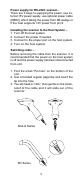
Power supply for RS-232C scanner– There are 3 ways to supplying the power, use external +5V power supply, use optional power cable (KBDC) which taking the power from KB wedge or if the host supports +5V power from pin 9. Installing the scanner to the Host System – 1. Turn off the host system. 2. Connect the power if needed. 3. Connect to the proper port on the host system. 4. Turn on the host system.
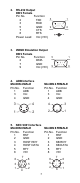
1.5 Pin Assignment A> Input Port for Mini Decoder DB 9 Male Pin No. Wand / CCD / Slot Reader Laser Scanner 1 N.C. S.O.S. 2 DATA DATA 3 N.C. N.C. 4 N.C. N.C. 5 N.C. TRIGGER 6 N.C. P. E. 7 GND GND 8 SHIELD SHIELD 9 +5V +5V 1 5 6 9 B> Output Port 1. PC Keyboard Output DIN 5 MALE DIN 5 FEMALE Pin No. Function Pin No. Function 1 HOST CLK 1 KB CLK 2 HOSTDATA 2 KBDATA 4 GND 4 GND 5 Vcc(+5V) 5 Vcc(+5V) 1 3 1 3 5 4 5 2 4 2 MiniDIN 6 MALE Pin No.
2. RS-232 Output DB 9 Female Pin No. Function 5 2 TXD 3 RXD 5 GND 9 7 CTS 8 RTS Power Lead Vcc (+5V) 3. WAND Emulation Output DB 9 Female Pin No. Function 2 DATA 7 GND 9 Vcc (+5V) 4. ADB Interface MiniDIN 4 MALE Pin No. Function 1 ADB 3 Vcc 4 GND 1 6 5 1 9 6 MiniDIN 4 FEMALE Pin No. Function 1 ADB 3 Vcc 4 GND 3 4 4 3 1 2 2 1 5. NEC 9801 Interface MiniDIN 8 MALE Pin No. Function 1 RST 2 GND 3 HOST RDY 4 HOST DATA 5 RTY 8 +5V 6 3 1 7 4 MiniDIN 8 FEMALE Pin No.
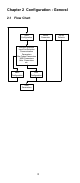
Chapter 2 Configuration - General 2.1 Flow Chart Start Configuration Recall Parameter Interface Selection Input Port Selection Communication Parameters Bar Codes Parameters MSR Parameters Misc .Parameters etc.
2.2 Loop of Programming The philosophy of programming parameters has been shown on the flow chart of 2.1. Basically user should 1. Scan Start of Configuration. 2. Scan all necessary labels for parameters that meet applications. 3. Scan End of Configuration to end the programming. 4. To permanently save the settings you programmed, just scan label for Save Parameters. 5. To go back to the Default Settings, just scan label for Set All Defaults. 2.
2.4 Main Page of Configuration Save Parameters %$ + / 0 Recall Stored Parameters %$ + / 1 Set All Defaults %$ + / 2 Start Configuration %$ + / 3 End Configuration %$ + / 4 Abort Configuration %$ + / 6 Version Information %$ + / 5 Save Parameters The parameter settings will be saved permanently. Recall Stored Parameters Replace the current parameters by the parameters you saved last time. Set All Defaults Set all the parameters to the factory default settings.
Chapter 3 Interface and Reading Mode Selection 3.1 Interface Selection %0 0 U0 RS232 Mode %0 0 U8 WAND Emulation %0 0 M2 OCIA Mode %0 0 M4 USB Mode %0 XO8 3.
3.
Ch.4 Communication Parameters 4.
D> Set Up Parity Even %0 YN7 Odd %0 YN2 Mark %0 YN3 Space %0 YN1 %0 YN0 E> Handshaking RTS/CTS Enable %0 1 8 8 ACK/NAK Enable %0 1 8 0 %0 1 4 4 XON/XOFF Enable %0 1 4 0 %0 3 K4 %0 3 K0 14
4.
B> Upper/Lower Case %0 3 3 0 Upper Case %0 3 3 1 Lower Case %0 3 3 2 C> Send Character by ALT Method Enable %0 3 O8 %0 3 O0 D> Select Numerical Pad ON %0 1 K4 %0 1 K0 16
4.
B> Time-out Between Characters <0 ms> %0 0 7 0 5 ms %0 0 7 1 10 ms %0 0 7 2 25 ms %0 0 7 3 50 ms %0 0 7 4 100 ms %0 0 7 5 200 ms %0 0 7 6 300 ms %0 0 7 7 18
4.
4.
Ch.5 Bar Codes & Others 5.
Interleave 25 OFF %0 GO8 Industrial 25 ON %0 GO0 %0 HO8 Matrix 25 ON %0 HO0 %0 I O8 CODE 93 ON %0 I O0 %0 KO8 CODE 11 ON %0 KO0 %0 L O8 China Postage ON %0 L O0 %0 MO8 MSI/PLESSEY ON %0 MO0 %0 NO8 %0 NO0 22
BC412 ON %0 OO8 Code 2 of 6 ON %0 OO0 %0 PO8 Telepen ON %0 PO0 %0 TO8 Reserved4 ON %0 TO0 %0 QO8 Reserved5 ON %0 QO0 %0 RO8 %0 RO0 Reserved6 ON %0 SO8 %0 SO0 Select All Bar Codes %1 A/ + 23
5.
5.
5.
D> Decode Asterisk Enable %0 E2 2 %0 E2 0 E> Set Up Code Length To set the fixed length: 1. Scan the "Begin" label of the desired set. 2. Go to the Decimal Value Tables in Appendix A, scan label(s) that represents the length to be read. 3. Scan the "Complete" label of the desired set. Repeat the steps 1 - 3 to set additional lengths. %4 E1 + Fix Length (2 Sets Available) 1. 1st Set Begin 2. Decimal Value (Appendix A) 3. 1st Set Complete %4 E0 0 %4 E0 1 1. 2nd Set Begin 2.
5.4 Code 128 Parameters A> Check Digit Transmission Do Not Calculate Check Digit %0 FN1 Calculate Check Digit & Transmit %0 FN7 %0 FN5 B> Append FNC2 ON %0 F8 8 %0 F8 0 C> Set Up Code Length To set the fixed length: 1. Scan the "Begin" label of the desired set. 2. Go to the Decimal Value Tables in Appendix A, scan label(s) that represents the length to be read. 3. Scan the "Complete" label of the desired set.
%4 F1 + Fix Length (2 Sets Available) 1. 1st Set Begin 2. Decimal Value (Appendix A) %4 F0 0 3. 1st Set Complete %4 F0 1 1. 2nd Set Begin 2. Decimal Value (Appendix A) %4 F0 0 3. 2nd Set Complete %4 F0 2 Minimum Length 1. Begin 2. Decimal Value (Appendix A) %2 + - / 3.
5.
D> Set Up Code Length To set the fixed length: 1. Scan the "Begin" label of the desired set. 2. Go to the Decimal Value Tables in Appendix A, scan label(s) that represents the length to be read. 3. Scan the "Complete" label of the desired set. Repeat the steps 1 - 3 to set additional lengths. %4 G1 + Fix Length (2 Sets Available) 1. 1st Set Begin 2. Decimal Value (Appendix A) %4 G0 0 3. 1st Set Complete %4 G0 1 1. 2nd Set Begin 2. Decimal Value (Appendix A) %4 G0 0 3.
5.6 Industrial 25 Parameters A> Check Digit Transmission %0 HN3 Calculate Check Digit & Transmit %0 HN7 Calculate Check Digit & Not Transmit %0 HN5 B> Set Up Code Length To set the fixed length: 1. Scan the "Begin" label of the desired set. 2. Go to the Decimal Value Tables in Appendix A, scan label(s) that represents the length to be read. 3. Scan the "Complete" label of the desired set. Repeat the steps 1 - 3 to set additional lengths.
%4 H1 + Fix Length (2 Sets Available) 1. 1st Set Begin 2. Decimal Value (Appendix A) %4 H0 0 3. 1st Set Complete %4 H0 1 1. 2nd Set Begin 2. Decimal Value (Appendix A) %4 H0 0 3. 2nd Set Complete %4 H0 2 Minimum Length 1. Begin 2. Decimal Value (Appendix A) %2 + - / 3.
5.7 Matrix 25 Parameters A> Check Digit Transmission %0 I N3 Calculate Check Digit & Transmit %0 I N7 Calculate Check Digit & Not Transmit %0 I N5 B> Set Up Code Length To set the fixed length: 1. Scan the "Begin" label of the desired set. 2. Go to the Decimal Value Tables in Appendix A, scan label(s) that represents the length to be read. 3. Scan the "Complete" label of the desired set. Repeat the steps 1 - 3 to set additional lengths.
%4 I 1 + Fix Length (2 Sets Available) 1. 1st Set Begin 2. Decimal Value (Appendix A) %4 I 0 0 3. 1st Set Complete %4 I 0 1 1. 2nd Set Begin 2. Decimal Value (Appendix A) %4 I 0 0 3. 2nd Set Complete %4 I 0 2 Minimum Length 1. Begin 2. Decimal Value (Appendix A) %2 + - / 3.
5.
C> Set Up Code Length To set the fixed length: 1. Scan the "Begin" label of the desired set. 2. Go to the Decimal Value Tables in Appendix A, scan label(s) that represents the length to be read. 3. Scan the "Complete" label of the desired set. Repeat the steps 1 - 3 to set additional lengths. %4 J 1 + Fix Length (2 Sets Available) 1. 1st Set Begin 2. Decimal Value (Appendix A) %4 J 0 0 3. 1st Set Complete %4 J 0 1 1. 2nd Set Begin 2. Decimal Value (Appendix A) %4 J 0 0 3.
5.9 Code 93 Parameters A> Check Digit Transmission %0 KN4 Do Not Calculate Check Digit %0 KN3 B> Set Up Code Length To set the fixed length: 1. Scan the "Begin" label of the desired set. 2. Go to the Decimal Value Tables in Appendix A, scan label(s) that represents the length to be read. 3. Scan the "Complete" label of the desired set. Repeat the steps 1 - 3 to set additional lengths.
%4 K1 + Fix Length (2 Sets Available) 1. 1st Set Begin 2. Decimal Value (Appendix A) %4 K0 0 3. 1st Set Complete %4 K0 1 1. 2nd Set Begin 2. Decimal Value (Appendix A) %4 K0 0 3. 2nd Set Complete %4 K0 2 Minimum Length 1. Begin 2. Decimal Value (Appendix A) %2 + - / 3.
5.10 Code 11 Parameters A> Check Digit Transmission Calculate Check 1 Digit & Transmit %0 L N3 %0 L N7 Calculate Check 1 Digit & Not Transmit Calculate Check 2 Digits & Transmit %0 L N5 %0 L N6 Calculate Check 2 Digits & Not Transmit %0 L N4 B> Set Up Code Length To set the fixed length: 1. Scan the "Begin" label of the desired set. 2. Go to the Decimal Value Tables in Appendix A, scan label(s) that represents the length to be read. 3.
%4 L 1 + Fix Length (2 Sets Available) 1. 1st Set Begin 2. Decimal Value (Appendix A) %4 L 0 0 3. 1st Set Complete %4 L 0 1 1. 2nd Set Begin 2. Decimal Value (Appendix A) %4 L 0 0 3. 2nd Set Complete %4 L 0 2 Minimum Length 1. Begin 2. Decimal Value (Appendix A) %2 + - / 3.
5.11 MSI/PLESSEY Code Parameters A> Check Digit Transmission Calculate Check Digit & Transmit %0 NN3 %0 NN7 Calculate Check Digit & Not Transmit %0 NN5 B> Set Up Code Length To set the fixed length: 1. Scan the "Begin" label of the desired set. 2. Go to the Decimal Value Tables in Appendix A, scan label(s) that represents the length to be read. 3. Scan the "Complete" label of the desired set. Repeat the steps 1 - 3 to set additional lengths.
%4 N1 + Fix Length (2 Sets Available) 1. 1st Set Begin 2. Decimal Value (Appendix A) %4 N0 0 3. 1st Set Complete %4 N0 1 1. 2nd Set Begin 2. Decimal Value (Appendix A) %4 N0 0 3. 2nd Set Complete %4 N0 2 Minimum Length 1. Begin 2. Decimal Value (Appendix A) %2 + - / 3.
5.12 BC 412 Code Parameters A> Check Digit Transmission Do Not Calculate Check Digit %0 ON3 %0 ON7 Calculate Check Digit & Not Transmit %0 ON5 B> Set Up Code Length To set the fixed length: 1. Scan the "Begin" label of the desired set. 2. Go to the Decimal Value Tables in Appendix A, scan label(s) that represents the length to be read. 3. Scan the "Complete" label of the desired set. Repeat the steps 1 - 3 to set additional lengths.
%4 O1 + Fix Length (2 Sets Available) 1. 1st Set Begin 2. Decimal Value (Appendix A) %4 O0 0 3. 1st Set Complete %4 O0 1 1. 2nd Set Begin 2. Decimal Value (Appendix A) %4 O0 0 3. 2nd Set Complete %4 O0 2 Minimum Length 1. Begin 2. Decimal Value (Appendix A) %2 + - / 3.
5.13 Code 2 of 6 Parameters A> Check Digit Transmission Do Not Calculate Check Digit %0 PN3 %0 PN7 Calculate Check Digit & Not Transmit %0 PN5 B> Set Up Code Length To set the fixed length: 1. Scan the "Begin" label of the desired set. 2. Go to the Decimal Value Tables in Appendix A, scan label(s) that represents the length to be read. 3. Scan the "Complete" label of the desired set. Repeat the steps 1 - 3 to set additional lengths.
%4 P1 + Fix Length (2 Sets Available) 1. 1st Set Begin 2. Decimal Value (Appendix A) %4 P0 0 3. 1st Set Complete %4 P0 1 1. 2nd Set Begin 2. Decimal Value (Appendix A) %4 P0 0 3. 2nd Set Complete %4 P0 2 Minimum Length 1. Begin 2. Decimal Value (Appendix A) %2 +- / 3.
5.14 Telepen Parameters A> Type of Code Telepen Numeric %0 T8 0 %0 T8 8 B> Check Digit Transmission Do Not Calculate Check Digit Calculate Check Digit & Transmit %0 TN3 %0 TN7 %0 TN5 C> Set Up Code Length To set the fixed length: 1. Scan the "Begin" label of the desired set. 2. Go to the Decimal Value Tables in Appendix A, scan label(s) that represents the length to be read. 3. Scan the "Complete" label of the desired set.
%4 T1 + Fix Length (2 Sets Available) 1. 1st Set Begin 2. Decimal Value (Appendix A) %4 T0 0 3. 1st Set Complete %4 T0 1 1. 2nd Set Begin 2. Decimal Value (Appendix A) %4 T0 0 3. 2nd Set Complete %4 T0 2 Minimum Length 1. Begin 2. Decimal Value (Appendix A) %2 +- / 3.
Ch.6 Miscellaneous Parameters 6.
Belgium %0 ZVA Portuguese %0 ZVB Denmark %0 ZVC Netherlands %0 ZVD Turkey %0 ZVE Reserved1 %0 ZVF 51
6.2 Bar Code ID ON %0 0 H1 %0 0 H0 Default %9 1 3 + With this function ON, a leading character will be added to the output string while scanning code, user may refer to the following table to know what kind of bar code is being scanned. Please refer to the table below for matching code ID of codes read in.
UPC-A UPC-E %9 1 A+ EAN-13/JAN-13 %9 1 B+ EAN-8/JAN-8 %9 1 Y+ CODE 39 %9 1 Z+ CODE 128 %9 1 E+ CODABAR/NW7 %9 1 F+ Interleave 25 %9 1 J + Industrial 25 %9 1 G+ Matrix 25 %9 1 H+ CODE 93 %9 1 I + CODE 11 %9 1 K+ China Postage %9 1 L + MSI/PLESSEY %9 1 M+ BC412 %9 1 N+ %9 1 O+ 53
Code 2 of 6 %9 1 P+ Telepen %9 1 T+ Reserved4 %9 1 Q+ Reserved5 %9 1 R+ Reserved6 %9 1 S+ 54
6.3 Reading Level Bar Equals High %0 3 I 2 %0 3 I 0 6.4 Accuracy <1 Time> 2 Times %0 1 3 0 3 Times %0 1 3 1 4 Times %0 1 3 2 %0 1 3 3 6.
6.6 Sensitivity of Continuous Reading Mode %0 3 8 8 Slow %0 3 8 0 6.7 Notebook Function Enable %0 3 4 4 %0 3 4 0 6.
6.9 Setup Deletion To setup the deletion of output characters: 1. Scan the label of the desired set below. 2. Scan the label of the desired symbology. 3. Go to theDecimal Value Tables inAppendixA, scan label(s) that represents the desired position to be deleted. 4. Scan the "Complete" label of "Character Position to be Deleted". 5. Go to theDecimal Value Tables inAppendixA, scan label(s) that represents the number of characters to be deleted. 6.
B> Symbologies Selection UPC-A UPC-E %8 1 A+ EAN-13/JAN-13 %8 1 B+ EAN-8/JAN-8 %8 1 Y+ CODE 39 %8 1 Z+ CODE 128 %8 1 E+ CODABAR/NW7 %8 1 F+ Interleave 25 %8 1 J + Industrial 25 %8 1 G+ Matrix 25 %8 1 H+ CODE 93 %8 1 I + CODE 11 %8 1 K+ China Postage %8 1 L + MSI/PLESSEY %8 1 M+ %8 1 N+ 58
BC412 Code 2 of 6 %8 1 O+ Telepen %8 1 P+ Resvered4 %8 1 T+ Resvered5 %8 1 Q+ %8 1 R+ All Codes %8 1 S+ None %8 1 4 + C> Character Position to be Deleted 1. Decimal Value (AppendixA) 2. Complete %8 2 0 + D> Number of Characters to be Deleted 1. Decimal Value (AppendixA) 2.
6.10 Setup Insertion To setup the insertion of output characters: 1. Scan the label of the desired set. 2. Scan the label of the desired symbology. 3. Go to theDecimal Value Tables inAppendix A, scan label(s) that represents the desired position to be inserted. 4. Scan the "Complete" label of "Character Position to be Inserted". 5. Go to the ASCII Tables in Appendix B or Function Key Tables in Appendix C, scan label(s) that represents the desired characters to be inserted. 6.
B> Symbologies Selection UPC-A UPC-E %5 1 A+ EAN-13/JAN-13 %5 1 B+ EAN-8/JAN-8 %5 1 Y+ CODE 39 %5 1 Z+ CODE 128 %5 1 E+ CODABAR/NW7 %5 1 F+ Interleave 25 %5 1 J + Industrial 25 %5 1 G+ Matrix 25 %5 1 H+ CODE 93 %5 1 I + CODE 11 %5 1 K+ China Postage %5 1 L + MSI/PLESSEY %5 1 M+ %5 1 N+ 61
BC412 Code 2 of 6 %5 1 O+ Telepen %5 1 P+ Resvered4 %5 1 T+ Resvered5 %5 1 Q+ %5 1 R+ All Codes %5 1 S+ None %5 1 4 + C> Character Position to be Inserted 1. Decimal Value (AppendixA) 2. Complete %5 2 0 + D> Characters to be Inserted 1. ASCII Table (Appendix B) 2.
6.
Appendix A Decimal Value Table 0 1 2 3 4 5 6 7 8 9 64
Appendix B ASCII Table NULL 00 SOH STX ETX 01 02 03 ENQ ACK 04 05 06 07 08 0A 0B 0D 0E 10 11 13 14 16 17 19 1A RS EM SUB ESC 1B SYN ETB CAN 18 DC3 DC4 NAK 15 DLE DC1 DC2 12 CR SO SI 0F LF VT FF 0C BEL BS HT 09 EOT FS GS 1C 1D 1E US 1F 65
SPACE 20 ! " 21 22 23 % 24 25 26 ( 27 28 29 + 2A 2B 2C .
40 B 41 42 43 E 44 45 46 H 47 48 49 K 4A 4B 4C N 4D 4E 4F Q 50 51 52 T 53 54 55 W 56 57 58 Z 59 5A 5B ] 5C 5D 5E 5F 67
60 b 61 62 63 e 64 65 66 h 67 68 69 k 6A 6B 6C n 6D 6E 6F q 70 71 72 t 73 74 75 w 76 77 78 z 79 7A 7B } 7C 7D 7E DEL 7F 68
Appendix C Function Key Table F1 F2 C0 C1 F3 C2 F4 F5 C3 C4 F6 C5 F7 F8 C6 C7 F9 C8 F10 F11 C9 CA F12 CB Insert Delete CC CD Home CE Page Up Page Down CF D0 End D1 Left Right D2 D3 Up D4 Down D5 69
Save Parameters %$ + / 0 Recall Stored Parameters %$ + / 1 Set All Defaults %$ + / 2 Start Configuration %$ + / 3 End Configuration %$ + / 4 Abort Configuration %$ + / 6 Version Information %$ + / 5 Ver 3.