
User's Manual
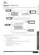
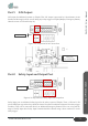
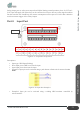
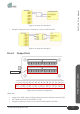
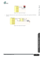
Table Of Contents
- ZALPHA 3.3 User Manual
- Copyright Notice
- Table of Contents
- Table of Figures
- Table of Tables
- 1. Preface
- 2. Safety
- 3. Getting Started
- 4. Product Presentation
- Section 1: About Zalpha
- Section 2: Modules of Zalpha
- Section 3: Safety Features
- Section 4: LED Indicators
- Section 5: Expansion IO
- Section 6: Main Features of Zalpha
- 5. Troubleshooting
- 6. Services and Maintenances
- 7. Disclaimer
- 8. Certification
- 9. Change Log

Product Presentation
52
www.dfautomation.com
ZALPHA 3.3 User Manual
Safety Output port are safety state output from Zalpha. During normal operation, these +S OUT and -
S OUT pin will supply 24V where they can be connected to a relay to drive any safety signal condition.
Do take note that user should keep the current consumption on these pins to be lower than 100mA to
avoid overcurrent trigger of the Safety Output.
Part 3: Input Port
Figure 4-37: Expansion IO Input Port
Descriptions:
• Input type: NPN Input (Sinking)
• Short Input pin to GND to activate the input
• Open Input pin to deactivate the input
• Example1: Input pin can be activated using a push button or limit switch connected to the
GND.
Figure 4-38: Input Port Example 1
• Example2: Input pin can be activated using a sinking NPN transistor controlled by
microcontroller.
Input 1-8