ZALPHA 3.3 USER MANUAL VERSION 1.
ZALPHA 3.3 User Manual ZALPHA 3.3 User Manual ZALPHA 3.3 User Manual Version 1.1 Khairul Dhinie Kamaruzaman DF Automation & Robotics Sdn. Bhd. Tel: +607-5623547 Fax: +607-5544269 Email: sales@dfautomation.com www.dfautomation.
T he information contained in here is the property of DF Automation & Robotics (M) Sdn. Bhd., and shall not be reproduced in whole or in part without prior written approval of DF Automation & Robotics (M) Sdn. Bhd. The information herein is subject to change without notice and should not be construed as a commitment by DF Automation & Robotics (M) Sdn. Bhd. The documentation is periodically reviewed and revised. DF Automation & Robotics (M) Sdn. Bhd.
ZALPHA 3.3 USER MANUAL........................................................................................................................................... 1 COPYRIGHT NOTICE ...................................................................................................................................................... 2 TABLE OF CONTENTS ....................................................................................................................................................
4. Create Task Template ........................................................................................................................ 27 Run the Task Template ...................................................................................................................... 28 CHARGING YOUR ZALPHA ......................................................................................................................... 28 SHUTTING DOWN ZALPHA ....................................................
Figure 1-1 Zalpha Standard AMR........................................................................................................................................... 8 Figure 3-1: Charging Station ................................................................................................................................................ 15 Figure 3-3: Charging Station of Zalpha ............................................................................................................................
Figure 4-22: Brake Release Button ...................................................................................................................................... 43 Figure 4-23: Steps to open manual line follow app ............................................................................................................. 43 Figure 4-24: Free Motor option Manual Line Follow app ....................................................................................................
Table 3-1: Junction vs Intersection ...................................................................................................................................... 20 Table 3-2: NavWiz Username and Password ....................................................................................................................... 26 Table 3-3: Task Template Action .........................................................................................................................................
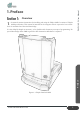
Overview T he manual contains instructions for installing and using the Zalpha AMR. It consists of Zalpha AMR specification. This manual is intended for the integrator who is expected to have a basic level of mechanical and electrical knowledge. Preface It is also helpful, though not necessary, to be familiar with elementary concepts of programming. No special knowledge about AMR in general or DF Automation & Robotics is required. ZALPHA 3.3 User Manual 1. Preface Figure 1-1 Zalpha Standard AMR www.
C ongratulations on the purchase of your Zalpha AMR by DF Automation & Robotics (M) Sdn. Bhd. The DF Zalpha AMR (Autonomous Mobile Robot) is a mobile robot that can be used to transport many different types of material including pallets, rolls, racks, carts, trolleys and containers. DF Zalpha AMR is configurable to use different navigation methods - magnetic track guided and trackless laser guided. With our NavWiz system, the automation of materials transportation will be ina-snap-of-finger.
Overview T his chapter contains important safety information, which must be read and understood by the integrator of Zalpha AMR. It is essential that all instructions and guidance provided in other chapters and parts of this manual are observed and followed. General Safety Symbol and Notes ZALPHA 3.3 User Manual 2. Safety Danger: Indicates an immanently hazardous situation that will result in death or severe personal injury, or major damage to the equipment, if proper precautions are not taken.
T he information does not cover how to design, install and operate a complete AMR application, nor does it cover all peripheral equipment that can influence the safety of the complete system. The complete system must be designed and installed in accordance with the safety requirements set forth in the standards and regulations of the country where the AMR is installed.
O ne of the most important things that an integrator needs to do is to make a risk assessment. In many countries this is required by law. The AMR itself is completed mobile robot, as the safety of the AMR installation depends on how the AMR is integrated.
ZALPHA 3.3 User Manual 3. Getting Started Packaging Details Part 1: Basic Components: One fully-assembled Zalpha with NavWiz system installed The AMR includes the Sensor Modules (front and rear bumper and a laser scanning obstacle sensor), Panel Module, left and right Drive Modules, a manual charging port, a charger contact and battery.
Optional Components: Extension Module With purchase of Zalpha Extension Module, the module will be assembled to Zalpha, unless otherwise stated. Hooking Module With purchase of Zalpha Hooking Module, the module will be assembled to Zalpha, unless otherwise stated. ZALPHA 3.3 User Manual Part 2: Note: Hooking Module will be bundled together with Extension Module. Towing Module With purchase of Zalpha Towing Module, the module will be assembled to Zalpha, unless otherwise stated.
E ach Zalpha AMR will have its dedicated charging station. In the ConfigPanel, the Station where the Charging Station is placed normally will be configured as the Home Station. Defining the Charging Station as the Home Station is to restrict all rotating actions of Zalpha at the Charging Station. By doing so, the AMR will approach the station in only one heading direction.
Charging Contact and Charging Station T he Charging Contact of Zalpha is located at the side of the AMR. The Charging Contact is configurable to either left or right side of the AMR. Changing side for the Charging Contact will involve some rewiring work. Please contact authorized personnel to perform the changes. Warning: Improper installation of the Charging Contact can cause damage to the AMR. Figure on the left shows the Charging Station of Zalpha.
ZALPHA 3.3 User Manual The charging station is recommended to be secured on the floor with provided wall plug before operation. Warning: Be extra careful when handling heavy equipment to avoid injury Figure 3-5: Zalpha Docking to Charging Station Getting Started Danger: Do not touch charging contact of Zalpha or charger while AMR is docking as it will result in electrical shock. www.dfautomation.
Charging Station Mounting ZALPHA 3.3 User Manual Part 2: Figure 3-6: Charging Station Mounting Drilling Dimension (not to scale) Getting Started After drilling the holes, install the M6 wall plug to each of the hole. Figure 3-7: M6 Wall Plug www.dfautomation.
T he basic navigation method of Zalpha is by tracing the magnetic field of the Track that lie on the floor. The Track of Zalpha is constructed using 50mm width magnetic adhesive tape. The magnetic field of the Track is in north pole face up order. The thickness of the magnetic tape is 2mm. ZALPHA 3.3 User Manual Track Specification Figure 3-8: Magnetic Tape with Adhesive Part 1: Junction Getting Started Junction is defined as the whisker in between a straight path.
Intersection Intersection is defined as the merging point of two paths that perpendicular to each other. Similar to Junction, Intersection also can serve as a checkpoint for the actions of Zalpha. ZALPHA 3.3 User Manual Part 2: Figure 3-10: Intersection Dimension Part 3: Comparison between Junction and Intersection Forward Reverse Rotate Left / Right U-turn Left / Right www.dfautomation.
Minimum Turning Radius ZALPHA 3.3 User Manual Part 4: Getting Started Figure 3-11: Track Minimum Curving Radius (measured in mm) www.dfautomation.
Part 1: ZALPHA 3.3 User Manual Powering Up Turn Reset Key If everything is fine, turn on with reset key. Mandatory: Zalpha will not be able to power on if the Reset Key switch is in OFF position as it will cut off the main power supply. Part 2: Release E-Stop Button Upon activation of emergency button, the movement of Zalpha will stop immediately. To release it, hold and turn the Emergency Stop button to the indicated direction on the Emergency Stop button.
P anel consists of Reset Key, Emergency Stop, Low Battery Indicator, ON/OFF Button, LCD Touchscreen, Start Button, Brake Release Button, Stop Button and Antenna. The function of each component is as below: Antenna Reset Key E-Stop Button ZALPHA 3.3 User Manual Panel of Zalpha Low Battery Indicator ON/OFF Button Screen Cover Touch Screen Reset Key Antenna Getting Started Start Button Mode Button Figure 3-12: Panel of Zalpha Standard www.dfautomation.
Emergency Stop: Emergency Stop button for user to trigger an immediate stop on the AMR Movement. Button needed to be manually released before resuming AMR Operation. Part 2: Low Battery Indicator: Low Battery Indicator will light when the battery level is lower than 20%. Operations are not recommended if the Low Battery Indicator was lit up. Caution: Operating the AMR under low battery level may cause the AMR sudden power down or unstable operation. Part 3: ZALPHA 3.
Stop Button: ZALPHA 3.3 User Manual Part 7: Stop Button served as an alternative for the “No” option in Confirm Action’s popup. Part 8: Antenna: Zalpha AMR’s Wi-Fi transmitter and receiver. Part 9: Reset Key: The function of Reset Key switch is to perform a hard reset the AMR System under special condition, e.g. Zalpha AMR was not able to perform a reboot under normal standard operation procedure. The key of the Reset Key switch should be kept by authorized personnel.
Connect to the same WIFI as AMR, open the web browser and key in the IP address, as simple as that! ZALPHA 3.3 User Manual Connect to NavWiz! Figure 3-13: NavWiz Interface Part 1: NavWiz PC NavWiz UserPanel and ConfigPanel can be accessed from a laptop or PC when they are connected to the same network. Type the IP address that displays on the LCD Panel of Zalpha into address bar of browser (Google Chrome Version 54.0 and above or Mozilla Firefox 49.0 and above).
Create Task Template ZALPHA 3.3 User Manual Part 3: Task Template is an important element in NavWiz System as it controls all operation of Zalpha. To access it, go to “NavWiz ConfigPanel” > System > Task Template and click on the “Add new task template button”. In order to test the functionality of Zalpha, the following will be a very brief guide on creating task template. Make sure that the box “Active” and “Toplevel template” is ticked. Please remember to save the changes.
Run the Task Template Now, in NavWiz, under “Task Runner”, you will be able to see the Task Template created previously. Click on it to run that Task Template and observe does Zalpha work as you expected. This will be able to test its functionality. Charging your Zalpha There are two methods of charging the Zalpha, auto or manual charging. The power rating of charger is 220V~240V AC by default. When battery level is lower than 20%, Low Battery Indicator will lit.
About Zalpha Zalpha is a powerful automatic guided vehicle (AMR) which can handle up to 500kg of towing payload. Zalpha is definitely a well-built solution to reduce manpower in warehouses, industrial factories and production lines. Zalpha is a user-friendly AMR which operates based on a web-based operating system called NavWiz. In NavWiz, different tasks and actions can be combined into a template systematically and the task runner will perform all the instructions accurately.
ZALPHA 3.3 User Manual Extension Product Presentation Figure 4-2: Zalpha with Extension Module www.dfautomation.
ZALPHA 3.3 User Manual Safety Features Bumper Laser Bumper Product Presentation Figure 4-3: Safety Features of Zalpha www.dfautomation.
Front and Rear Laser Obstacle Sensor ZALPHA 3.3 User Manual Part 1: Zalpha front laser scanning Obstacle Sensor is located underneath the Panel Module. While Zalpha AMR is moving, the laser scanning Obstacle Sensor will scan and locate obstacle in front of Zalpha. When obstacle is presence, the Obstacle Sensor will alert Zalpha to slow down as it gets closer to the obstacle and stop when Zalpha is too close to the obstacle.
Laser Scanning Area ZALPHA 3.3 User Manual Part 2: There are three layers in the Laser Scanning Area - Far, Middle and Near. Table 4-1: Laser Scanning Area Colour Code Color Code Area Far Middle Near Laser scanning profile for Forward Movement: Max Allowed Speed (m/s) 0.45 0.30 0.15 Product Presentation Color Code Figure 4-5: Front Movement Laser Scanning profile www.dfautomation.
Color Code ZALPHA 3.3 User Manual Laser scanning profile for Reverse Movement Max Allowed Speed (m/s) 0.45 0.30 0.15 Figure 4-6: Reverse Movement Laser Scanning Profile Product Presentation Info: Rear Obstacle Sensor is not included in standard package of Zalpha AMR. It is available as an optional purchase. www.dfautomation.
Color Code ZALPHA 3.3 User Manual Laser scanning profile for Rotate Left Movement Max Allowed Speed (rad/s) Unlimited Unlimited 0.15 Figure 4-7: Rotate Left Movement Laser Scanning Profile www.dfautomation.com Product Presentation Info: Rear Obstacle Sensor is not included in standard package of Zalpha AMR. It is available as an optional purchase.
Color Code ZALPHA 3.3 User Manual Laser scanning profile for Rotate Right Movement Max Allowed Speed (rad/s) Unlimited Unlimited 0.15 Figure 4-8: Rotate Right Movement Laser Scanning Profile www.dfautomation.com Product Presentation Info: Rear Obstacle Sensor is not included in standard package of Zalpha AMR. It is available as an optional purchase.
Laser Scanning Obstacle Sensor Limitation ZALPHA 3.3 User Manual Part 3: Figure 4-9: Laser Scanning Obstacle Sensor Limitation Product Presentation The sensing plane of the laser scanning Obstacle Sensor of Zalpha AMR is approximately 140mm above ground level. Therefore, Zalpha AMR is unable to detect obstacle that lower than this height using the laser scanning Obstacle Sensor. To counter this limitation, Zalpha AMR is equipped with another important safety component - Bumper. www.dfautomation.
Hokuyo Obstacle Sensor Laser Scanning Profile Hokuyo Obstacle Sensor is used to detect obstacle and blockage along the navigation path. If there is any obstacle blocking the way of AMR movement, AMR will be stopped immediately. The sensor is configurable and the sensing profile can be set via the Hokuyo software (Area Designer). Area designer can be downloaded from Hokuyo official website. (https://www.hokuyo-aut.jp/) Connecting Sensor to PC ZALPHA 3.3 User Manual Part 4: 1.
ZALPHA 3.3 User Manual Profile Program and Upload Figure 4-13: Click on the icon to access to edit page 1. Click the “Pen” icon to access to the edit page (as shown above) Figure 4-14: Click on the icon to read the sensor profile from Sensor Figure 4-15: Sensor Profile 4. Profile Select: • Profile 1: Sensing profile for moving Forward • Profile 2: Sensing profile for turning Right • Profile 3: Sensing profile for turning Left 5.
8. Once the edit is done, click “Write to sensor” to program the profile to the sensor (As shown below) ZALPHA 3.3 User Manual 7. For better adjustment quality, it’s advisable to edit the sensing profile on Value Edit session (As shown below) Figure 4-16: Value Edit session for accurate area adjustment Product Presentation Figure 4-17: Program the Sensor www.dfautomation.
1. Sensor profile can be saved and restore. 2. Click on the “save” icon to save the profile (As shown below). The file will be saved in (.arax) format. Figure 4-18: Save the Profile (.arax) to Local Drive ZALPHA 3.3 User Manual Backup and Restore 3. To restore the profile, just click File > Open, and select the .arax file that you wish to restore. Then just execute “Write to sensor” to program the profile to the sensor Figure 4-19: Load the Profile (.
Front and Rear Bumper ZALPHA 3.3 User Manual Part 5: Bumper Figure 4-20: Front Bumper on Zalpha When the Bumper of Zalpha contacted with obstacle, Zalpha will stop its movement and the braking mechanism will be engaged immediately. The Bumper of Zalpha AMR is made of foam-filled cushion which designed to reduce the impact when contact with obstacle. Part 6: Emergency Stop Button E-Stop Button Emergency Stop button is a manual control device.
External Safety Input External Safety Input allows user to add additional safety trigger device. This Safety Input port can be access through Expansion IO Panel. Brake The brake of Zalpha will always be engaged even after power off. Brake Release button is a function to allow user to push/move Zalpha freely. ZALPHA 3.3 User Manual Part 7: In order to release the brake, it requires user to press and hold on the button.
ZALPHA 3.3 User Manual 3. In Manual Line Follow app window, toggle the Free Motor option. Push the Brake Release button to push Zalpha AMR freely. Figure 4-24: Free Motor option Manual Line Follow app Safety Measure of Manual Charging Charger Connected Safety Trigger is a safety feature that prevent Zalpha AMR from moving if the Manual Charging Port is connected with Charger.
Safety Trigger Resume Sequences In case of Safety Trigger, please follow the safety resume sequence to resume normal operation: Front and Rear Obstacle Sensor Safety Trigger 1. Upon sensing of obstacle inside the laser scanning profile, Zalpha AMR will stop its current operation immediately and a Safety Triggered with Obstacle blocked message as shown in figure below will be shown on the LCD Touchscreen ZALPHA 3.
1. Upon the activation of either Front or Rear Bumper, AMR will stop its current operation immediately and a Safety Triggered with Bumper blocked message will be shown on the LCD Touchscreen as shown in figure below. ZALPHA 3.3 User Manual Front and Rear Bumper Safety Trigger Figure 4-27: Bumper Blocked Safety Triggered Message Product Presentation 2. Clear the obstacle at the Bumper sensor. A Safety Resume message as in figure below will be shown Figure 4-28: Safety Resume Message 3.
1. Upon manual activation of the Emergency Stop button, Zalpha AMR will stop its current operation immediately and a Safety Trigger message with Emergency button pressed will be shown on the LCD Touchscreen. ZALPHA 3.3 User Manual Emergency Stop Safety Trigger Figure 4-29: Emergency Button Pressed Safety Triggered Product Presentation 2.
1. Upon the start of AMR operation with the manual charging cable connected, the operation will be stop immediately and a Safety Triggered popup with Charger connected message will be shown on the LCD Touchscreen. ZALPHA 3.3 User Manual Manual Charging Safety Trigger Figure 4-31: Charger Connected Safety Triggered Message Product Presentation 2. Remove the manual charging cable that is connected to the Manual Charging Port 3.
LED Indicators shows different status of Zalpha during operation. Colour change is obvious and clear to provide immediate signal to users.
Zalpha comes with expansion IO port for the expansion of feature on Zalpha (payload handle). Main feature under Expansion IO port. Input Port Power/Safety Port ZALPHA 3.3 User Manual Expansion IO Output Port Figure 4-33: Zalpha Standard and Extension Expansion IO Power/Safety Port Input Port Output Port Recommended replacement connector type for these ports. By default, all the required connected will be provided on the Zalpha.
24V Output 24V output for additional actuator on Zalpha. This 24V output is protected by 10A miniature circuit breaker and this supply will be cut off during any safety trigger on Zalpha (Bumper, Emergency Button, Obstacle sensor or External Safety In). ZALPHA 3.
Part 3: Input Port Input 1-8 ZALPHA 3.3 User Manual Safety Output port are safety state output from Zalpha. During normal operation, these +S OUT and S OUT pin will supply 24V where they can be connected to a relay to drive any safety signal condition. Do take note that user should keep the current consumption on these pins to be lower than 100mA to avoid overcurrent trigger of the Safety Output.
ZALPHA 3.3 User Manual Figure 4-39: Input Port Example 2 • Example3: Input pin can be activated by a relay controlled by PLC. Figure 4-40: Input Port Example 3 Part 4: Output Port Product Presentation Output 1-8 Figure 4-41: Expansion IO Output Port Output Port: • • • Output Type: NPN Output (Sinking), Maximum current 250mA protected by PTC 24V Output: Protected by internal fuse (1.5A) Example1: Output pin can be used to control small load like 24V LED. www.dfautomation.
• Example2: Output pin can be used to activate relay for higher current application like Motor activation. ZALPHA 3.3 User Manual Figure 4-42: Output Port Example 1 Product Presentation Figure 4-43: Output Port Example 2 www.dfautomation.
✓ Modular body structure Zalpha is built with modular parts making it easy for servicing and maintenance ✓ Automatic charging system Zalpha can automatically charge itself to ensure 24-hour continuous operation ✓ User-friendly operation system, NavWiz User is able to draw and plan topological map to run Zalpha.
Following are some of the commonly found error that can be encountered from Zalpha AMR. Provided together is the flow and guide to troubleshoot and find the root cause of the problem. Please contact DF Automation & Robotics if you need further technical assistance. Table 5-1. Troubleshooting Guide Zalpha wouldn’t stop when obstacle is in front. Zalpha wouldn’t stop after bumper is hit. Buttons (Emergency button, start, stop, on/off).
F Automation & Robotics Sdn. Bhd. continue to improve reliability and performance of its product, and therefore reserves the right to upgrade the product without prior warning. DF Automation & Robotics Sdn. Bhd. takes every care that the contents of this documentation are precise and correct, but takes no responsibility for any errors or missing information. DF Automation & robotics Sdn. Bhd. is not liable for any accidents or mishaps due to the misuse of the product. D 8. Certification • • ZALPHA 3.
FCC Statement This device complies with Part 15 of the FCC Rules. Operation is subject to the following two conditions: (1)This device may not cause harmful interference. (2)This device must accept any interference received, including interference that may cause undesired operation. 2. Changes or modifications not expressly approved by the party responsible for compliance could void the user’s authority to operate the equipment.
www.dfautomation.com 59 Certification ZALPHA 3.
Date 30/10/2020 25/11/2020 Changes First changelog Update figure with low resolution Change front and back cover page back to color Revise Intended Use section Revise table font to Calibri Remove document version on side bar Change Log Version 1.0 1.1 ZALPHA 3.3 User Manual 9. Change Log www.dfautomation.
ZALPHA 3.3 User Manual DF Automation and Robotics Sdn. Bhd. Reg No.(1006594V) 5, Jalan Impian Emas 18, Taman Impian Emas, 81300 Skudai, Johor, Malaysia Change Log Tel: +607-5623547 Fax: +607-5544269 Email : sales@dfautomation.com Website : www.dfautomation.com www.dfautomation.