
User guide


4
INSTALLATION INSTRUCTIONS
All washers must be installed in accordance with all local, state and
national building, electrical, plumbing and other codes in effect.
WARNING - THESE INSTALLATION AND SERVICING INSTRUCTIONS ARE FOR
USE BY QUALIFIED PERSONNEL ONLY. TO AVOID INJURY AND ELECTRIC
SHOCK DO NOT PERFORM ANY SERVICING UNLESS QUALIFIED.
FOUNDATION REQUIREMENTS
This machine is designed for use on or over bare concrete floor - not to be
used above combustible flooring. The washer must be securely bolted to a
substantial concrete floor, or mounted upon a suitable base which is, in turn,
securely bolted to a substantial concrete floor. CARE MUST BE STRESSED WITH
ALL FOUNDATION WORK TO INSURE A STABLE UNIT INSTALLATION, ELIMINATING
POSSIBILITIES OF EXCESSIVE VIBRATION. All installations must be made on sound
concrete floors, 6" or thicker. Anchor bolts must be of a quality grade and a
minimum of 5/8" diameter. Four (4) mounting bolts must be used.
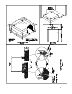
MOUNTING
A concrete pedestal or steel mounting base which elevates the machine
approximately 6" above the floor level is recommended to provide easy access to
the loading door. Actual base height should be determined by application
considering access to loading door, access to soap dispenser and height of
loading carts. Allow a minimum of 24" of clearance behind the rear of the
machine, to provide access for motor removal. Refer to Fig. 1-1 & 1-2 for
machine bolt-down dimensions. Refer to Fig. 2 for overall washer dimensions.
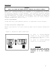
If an elevated concrete pedestal is desired, it should be embedded into the
existing floor. Anchor bolts should be 5/8" x 8", grade 5 or better, headed by
a 4 inch square fish plate and should protrude 1 7/8 inches above the finished
surface of the pedestal. EXPANSION ANCHORS ARE NOT RECOMMENDED FOR USE IN
CONCRETE FLOORS OR PEDESTALS, BECAUSE THE ANCHORS ARE TOO CLOSE TO AN EDGE,
CAUSING IT TO BREAK OUT. (See Fig. 1-1 and 1-3.)
PLUMBING
Water supply hoses are furnished with each machine. The threaded connections
on the hoses are 3/4-11 2 NHT.
Separate hot and cold water lines must be provided, maintaining 30 PSI to 120
PSI water flow pressure.
DRAIN
The drain outlet tube at the rear of the machine is 3 inches in diameter. Any
drain hose used must be lower than the drain valve to assure proper draining.