MPEG4 Network Camera with Pan/Tilt User’s Manual
Before You Use This Product The use of surveillance devices may be prohibited by law in your country. The Network Camera is not only a high-performance web-ready camera but also can be part of a flexible surveillance system. It is the user’s responsibility to ensure that the operation of such devices is legal before installing this unit for its intended use. It is important to first verify that all contents received are complete according to the list in the "Package Contents" chapter.
Before You Use This Product 2 Package Contents 4 Hardware Installation 5 Software Installation 7 Initial Access to the Network Camera 10 How to Use 11 Authentication 11 Installing Plug-in 12 Primary User’s Capabilities 12 Primary User’s Capabilities 13 Administrator’s Capabilities 17 Definitions in Configuration 27 System Parameters 28 User Group Administration 29 Network Settings 30 Mail & FTP 33 Video Codec Parameters 35 Motion Detection 36 Application Setup 38 Camera
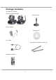
Package Contents The Network Camera (Wire or Wireless Model) Camera stand Power adapter Software CD A/V Cable Antennas for wireless model only Remote Controller 4
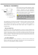
Hardware Installation Please verify that your product package contains all the accessories listed in the foregoing Package Contents. Wireless model only Depending on the user’s application, an Ethernet cable may be needed. The Ethernet cable should meet the specs of UTP Category 5 and not exceed 100 meters in length. Connect the power adapter jack to the Network Camera before plugging in to the power socket. This will reduce the risk of accidental electric shock.
To install in wireless LAN (Wireless Model Only) If the Ethernet is not available while power on, the Network Camera will search for any access point with the SSID “default”. Once any access point is found, the LED will turn green to wait for installation. If the network environment cannot meet the default settings, install Network Camera in Ethernet to proceed with wireless LAN configuration.
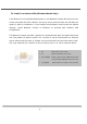
Software Installation In this manual, "User" refers to whoever has access to the Network Camera, and "Administrator" refers to the person who can configure the Network Camera and grant user access to the camera. At the end of the hardware installation, the Administrator must place the product software CD into the CD-ROM drive of the PC running in MS Windows. An auto-run program will pop up (If the program is not on auto-run, go to the root directory of the software CD and click on “autorun.exe”).
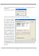
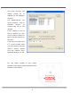
Upon IP installer’s start up, a searching box will pop up. This program searches for the Network Cameras on the same LAN: After searching the LAN, the main window of IP installer will pop up. The IP addresses shown in the "Current IP Address" field reflect those on the local network. They may be from the DHCP server. If there is no DHCP server, the camera will try to find a free IP address (this takes from 15 second to 3 minutes, depending on the LAN status).
The UPnP function will always assign an IP address for the Network Camera. The Administrator click on button selected can “Link to device” to connect the I.E. to the camera. If the camera is not on the IP installer list, click on the “Search” button to search for the camera on the LAN. If you can not connect the I.E. to the Camera after you click “Link to selected device” find the button. Please solution from Appendix B Page.
Initial Access to the Network Camera Check Network Settings The Network Camera can be connected either before or immediately after software installation onto the Local Area Network. The Administrator should complete the network settings on the configuration page, including the correct subnet mask and IP address of gateway and DNS. Ask your network administrator or Internet service provider for the detail information.
How to Use Authentication After opening the Web browser and typing in the URL of the Network Camera, a dialogue window pops up to request a username and password. Upon successful authentication, the following figure is displayed. The foreground is the login window and the background shows the message if authentication fails. The user may check the option box to save the password for future convenience. This option is not available to the Administrator for obvious reason.
Installing Plug-in For the initial access to the Network Camera in Windows, the web browser may prompt for permission to install a new plug-in that is the Network Camera. Permission request depends on the Internet security settings of the user’s PC or notebook. If the highest security level is set, the computer may prohibit any installation and execution attempt. This plug-in has been registered for certificate and is used to display the video in the browser. Users may click on to proceed.
Primary User’s Capabilities Main Screen with Camera View The main page layout has three parts: Configuration functions: The camera can be configured using these user interfaces. Camera View: What the camera sees. Pan/Tilt control buttons: These buttons provide a command interface to control the aim of the camera. Click on the configuration link to the left of the image window to enter the configuration page.
Clicking on this button links you to the client setting pages, please check the following session for more details. “Configuration” Only the Administrator can access camera configurations. The Camera View: The information bar at the top of the camera view shows the connection type to the Network Camera and the current date/time. The camera view provides not only the live video, but also a way to aim the Network Camera to different target.
Client Settings At the initial access to the “Connection type” page in Windows, the web browser will ask for a new plug-in installation, the plug-in being the Network Camera. This plug-in has been registered for certification and can be used to change the parameters at the client’s site. The user may click on to install the plug-in. If the web browser does not allow the user to complete the installation, check the Internet security to lower the security level or contact your IT or networking supervisor.
The TCP protocol allows for less packet loss and produce a more accurate video display. The downside with this protocol is that the real-time effect is worse than that with the UDP protocol. The HTTP protocol must be selected if the network is protected by a firewall and it only allows HTTP Port (80) to be opened. In this mode, audio will not be sent and only video is operational. If no special need is required, UDP protocol is recommended.
Administrator’s Capabilities Fine-Tuning for Best Performance There are a few choices the Administrator is allowed to maximize the capabilities of the Network Camera. Best performance generally equates to the fastest image refresh rate with the best video quality, and at the lowest network bandwidth as possible. The three factors, “Maximum frame rate”, “Fix bit rate”, and “Fix quality” on the Video Configuration page, are correlative to allow for achieving the best performance possible.
to 25 fps or 30 fps. If you are shooting fast-moving images, you may want to slow the maximum frame rate down to 20 fps in order to lower the rate of data transmission. This allows for better video quality and the human eyes cannot readily detect the differences between those of 20, 25, or 30 frames per second. If your network bandwidth is below 384 Kbps, set the “Fix bit rate” according to your bandwidth and try to get the best performance by fine-tuning with the “Maximum frame rate”.
Opening Accounts for New Users Protect Network Camera by passwords 1 2 3 4 Network Camera is shipped without any password by default. That means everyone can access Network Camera including the configuration as long as the IP address is known. It is necessary to assign a password if Network Camera is intended to be 1 to enable protection. This password accessed by others. Type a new word twice in ○ is used to identify the administrator. Then add an account with user name and 2 .
4 More flexible options for viewers ○ The first option allows anyone uses “demo” as the user name to view without password. The Administrator can also decide if more viewers are allowed to watch the video if the viewers exceed the limit. The overloaded viewers will have snapshot mode instead. Building a Multimedia Web Attraction Site Demo on multiple sites – mid-scale service The Network Camera can allow ten visitors to view on-line simultaneously.
If the web server space has FTP service Set the Network Camera up as an FTP client to upload the pictures. The access to the Network Camera will be independent of the number of viewers and the picture quality will remain constant. 1. Click on “Configuration” on the homepage, 2. Click on “Network” in the left column, 3. Fill in the FTP related settings including server, user name and password, as well as the upload path if it is specified by the web space, 4.
successfully uploaded to the correct folder, 10. Prepare a homepage with the embedded image reference to the image file uploaded via FTP in advance. If the web space has no FTP service An auto-refresh homepage can be used to periodically poll the newest image from the Network Camera. It is most efficient if using a free web space provider as the FTP service may be limiting. 1. Prepare an auto-refresh homepage as the following example.
Building a Security Application The Administrator combine options can on the application page to perform many useful security applications. There are two trigger sources coming from attached devices, such as for motion detection. There are also two kinds of actions responding to such events, including uploading snapshots over the Internet and driving other attached devices. To snapshots, upload the User can the choose either email or FTP according to user’s needs.
6. Set the delay to take snapshots after event to capture the direction of the moving objects, Send snapshots when motion is detected If no external sensor is available, the Administrator can use the built-in motion detection to monitor any movement and sends snapshots via email for security check. Enable 7. Click on “Motion detection” in the left column, 8. Check “Enable motion detection”, 9. Click on “New” to have a new window to monitor video, 10. Type in a name to identify the new window, 11.
13. Clicking on “Save” enables the activity display. Green means the motion in the window is under the watermark set by the Administrator and red means it is over the watermark, 14. Click on “Application” in the left column, 15. Check on the window name set in Step 10, 16. Check “Upload snapshots while motion detected”, if e-mailing the snapshots is preferred, 17. Check “Send snapshots by email”, 18. Click on “Save” to validate. ※ Remark Weekly schedule can work alone.
※ Software Revision Upgrade Customers can obtain the up-to-date software from the distributor. An easy-to-use Upgrade Wizard is provided to upgrade the Network Camera with just a few clicks. The upgrade function is opened to the Administrator only. To upgrade the system, follow the procedures below. 1. Download the firmware file named “FLASH.BIN” from the appropriate product folder. 2. Run the Upgrade Wizard and proceed following the prompts. Refer to the instructions of the Upgrade Wizard for details. 3.
Definitions in Configuration Only the Administrator can access system configuration. Each category in the left column will be explained in the following pages. The bold texts are the specific phrases on the Option pages. The Administrator may type the URL below the figure to directly enter the frame page of configuration. If the Administrator also wants to set certain options through the URL, read the reference appendix for details. http:///setup/config.
System Parameters "Host name" The text displays the title at the top of the main page. “Turn off the LED indicator” Check this option to shut off the LED beside the lens. It can prevent the camera’s operation being noticed. "Keep current date and time" Click on this to reserve the current date and time of the Network Camera. An internal real-time clock maintains the date and time even when the power of the system is turned off.
User Group Administration “Root password” Change the Administrator’s password by typing in the new password identically in both text boxes. The typed entries will be displayed as asterisks for security purposes. After pressing , the web browser will ask the Administrator for the new password for access. “Add user” Type the new user's name and password and press to insert the new entry. The new user will be displayed in the user name list. There is a maximum of twenty user accounts.
Network Settings Any changes made on this page will restart the system in order to validate the changes. Make sure every field is entered correctly before clicking on . "Reset IP address at next boot", the default status is checked to avoid erroneous entries during installation. This can be tedious having to perform software installation whenever the Network Camera starts. Therefore, once the network settings, especially the IP address, have been entered correctly, uncheck this option.
address is 192.168.0.100 from 80 to 8080, the User must type in the web browser “http://192.168.0.100:8080” instead of “http://192.168.0.100”. Streaming “Control channel port” This can be something other than the default port 5001 in order to work with the port opened by the firewall. “Audio channel port” This can be something other than the default port 5002 in order to work with the port opened by the firewall.
“Preamble”, either “Long preamble” or “Short preamble” defines the length of the CRC block (Cyclic Redundancy Check is a common technique for detecting data transmission errors) for communication between the Access Point and the roaming wireless device. Long Preamble is the default setting. Note: High network traffic areas should use the shorter preamble type. “Data encryption” Checking the box to enable the data encryption. By default it is disabled. “Auth.
Mail & FTP SMTP “SMTP (mail) server 1” The domain name or IP address of the external email server. “Recipient email address 1” The email address of the recipients for snapshots or log file. Multiple recipients must be separated by semicolons, ‘;’. “SMTP (mail) server 2” The domain name or IP address of another email server once the previous server is unreachable. “Recipient email address 2” The email addresses of the recipients for the backup server.
“2nd FTP user name” Granted user name on the backup FTP server. “2nd FTP password” Granted password on the backup FTP server. “2nd FTP remote folder” Granted folder on the backup FTP server. “Secondary FTP passive mode” Passive mode setting for the backup FTP server. address is 192.168.0.100 from 80 to 8080, the User must type in the web browser “http://192.168.0.100:8080” instead of “http://192.168.0.100”. Some invalid settings may cause the system failing to respond.
Video Codec Parameters “Text on video” The text will be displayed in the black bar above the video window with a timestamp. The timestamp is captured from the date and time of the Network Camera that is maintained by a built-in real-time clock. “Color” Select either for color or monochrome video display. "Size" There are three options for two video sizes. “Half” is the quarter size of “Normal”. “Half x 2” has the same video size as “Normal” but of a lesser quality, while consuming less network bandwidth.
Motion Detection “Enable motion detection” Check this option to turn on motion detection. Click on this button to add a new window. At most three windows can exist simultaneously. Use the mouse to click, hold, and drag the window frame to resize or the title bar to move. Clicking on the ‘x’ at the upper right-hand corner of the window to delete the window. Remember to save in order to validate the changes. Click on this button to save the related window settings.
Application Setup Weekly Schedule “Sun” ~ “Sat” Select the days of the week to perform the following operations. “Snapshots begin at” Set the time to start operations. “Snapshots stop at” Set the time to stop operations. Setting identical begin time and stop time means 24-hour operation. Event Operation “Delay second(s) before detecting next event” Set the time delay before restarting to check on the triggering condition when the current condition is triggered.
“Reset output” Select and save this option to reset the external device at the digital output to return to the original state. Sequential Operation “Snapshot every second(s)” The Network Camera will send snapshots at the specified intervals to the external server using the method selected below. Remember: This operation is still subject to the conditions set in the weekly schedule. “Send snapshots by email” This selects the uploading method following the intervals set above. The snapshot named “video.
Camera Control Camera control Preset function area On the Camera Control page, there are two main function control areas: Camera Control Area The pan and tilt functions can be controlled with these buttons. The “Left” button aims the camera to the left; the “Right”, “Up”, and “Down” buttons aim the camera accordingly. The “Home” button aims the camera to the center. “Pan speed” This controls the range of the horizontal movement of the camera.
Preset Function Area ”Enable IR control” Checking this box allows the Administrator to enable the IR controller to move the aim of the camera. To allow controls only through URL commands or web pages, leave this box unchecked. ”Current position”, If the User wants to save the current view as a preset location, enter a name for each of the current video view at “current position” and click on the “Add” button. The camera allows for 20 preset locations.
UPnP and DDNS Settings “Enable DDNS” This option turns on the DDNS function. “Provider” The provider list contains four hosts that provide DDNS services. Please connect to the service provider’s website to make sure the service charges. “Host name” If the User wants to use DDNS service, this field must be filled. Please input the hostname that is registered in the DDNS server. “Username/E-mail” The Username or E-mail field is necessary for logging in the DDNS server or notify the User of the new IP address.
Remote Controller The Network Camera with Pan/Tilt provides a remote controller to command the camera’s pan/tilt and other functions. The direction control part provides the function as on the main web page. The Pan/Patrol/Stop functions are also the same as on the main web page. Direction control area Auto movement control area “Auto Patrol” This button commands the camera to patrol between the preset positions on the patrol list that was set on the “Camera control page”.
Viewing System Log Click on the link on the configuration page to view the system log file. The content of this file provides useful information about configuration and connections after system boot-up. Viewing System Parameters Click on this link on the configuration page to view the entire system’s parameter set. The content is the same as those in CONFIG.INI. Factory Default “Factory default” Click on this link on the configuration page to restore factory default settings.
Configuring the Network Camera behind a IP Sharing (Router) If you are using a IP Sharing to share the Internet with one or more PCs, and IP Camera connected within LAN. These steps describe how to configured to allow remote viewing of the camera over the Internet. You will need: •The Network Camera •Ethernet Cable*1 •A Wired or Wireless IP Sharing (Router) such as D-Link DI-604 •Ethernet based PC for system configuration Make sure the IP Camera is firmly connected to the IP Sharing.
To find out what your IP Sharing’s WAN IP address is, for D-Link DI-604 example, go to the status menu on your IP Sharing the WAN information for your IP Sharing. The WAN IP address will be the address that your will need to type in your web browser to view your Network Camera over the Internet.
Appendix A. Troubleshooting Status LED After powering up, the Network Camera performs a self-diagnostic to detect any hardware defects. The following table lists the LED patterns in general. In case of any fatal error, the LED will blink in a pattern other than those below.
B. Frequently Asked Questions Q What if I forget my password? A After the Administrator's password has been assigned, every access to the Network Camera needs authentication. If you are one of the managed users, you have to ask the Administrator for the password. If you are the Administrator, there is no way to recover the root password except by restoring the factory default settings. Refer to Appendix A for the procedures.
A Yes. There are flip and mirror options in the video configuration page to correct the images for upside down installation. Q The image is not clear enough. A Rotate the lens to adjust the focus after the Network Camera has been installed in the proper position. The image settings and white balance can be fine tuned to achieve the best visual effect. Also notice the power line frequency must match the local utility to synchronize and minimize the effect of flickering florescent lights.
A The MPEG4 codec engine can process up to 30 frames per second internally. However, the total performance is subject to many coefficients such as: 1. Network throughput, 2. Bandwidth share, 3. Number of users, 4. The complicated/detailed objects and movement in view, 5. The power of your PC or notebook computer that is responsible for displaying images.
3. Change your PC’s IP address from 192.168.300.25 to 192.168.0.25. To verify make sure the first 3 sections of the IP address of the Network Camera corresponds to the first 3 sections of the PC. But you can not set the same IP address of Network Camera and your PC. 4. Restart Computer 5. Click the “IP Installer” button, find the Camera and click on “Link to selected device” button, now you will connect the I.E. to the Camera. 6. Check Page.12 to Install Plun-in. 7.
C. URL Commands of the Network Camera For some customers who already have their own web site or web control application, the Network Camera can be easily integrated through convenient URLs. This section lists the commands in URL format corresponding to the basic functions of the Network Camera. Capture Update Snapshot of JPEG Image /cgi-bin/video.jpg The Network Camera will return the most up-to-date snapshot in JPEG format. Query Status of the Digital Input /cgi-bin/getdi.
Restart the Network Camera without warning.
Page URL The configuration page has a frame layout including an option list frame and an option page frame. Referenced URLs, except for the configuration page, direct users to the option page frame only. Some pages, such as image quality setting and preset setting, are opened in new windows for preview. Only the Administrator can access these URLs. Homepage name Referenced URL Client settings page /client.html configuration page /setup/config.html system option /setup/system.
General Format of Command URL Every configuration can be set through URL with the POST method by the Administrator only. URL[?[name=value][&name=value]……] POST root System Configuration URL URL: /setup/system.
Security Configuration URL URL: /setup/security.
smtp2 secondary SMTP server mailto2 returnemail ftpp FTP port ftp1 primary FTP server ftpuser1 ftppass1 ftpfolder1
host 2 DynDDNS.org(Custom) 3 TZO.com 4 dhs.org The hostname of the Network Camera usermail username or mail The login username of DDNS server or the email address registered in DDNS server. passkey password or key The login password of DDNS server or the key given by the DDNS server. enupnp anything Enable UPnP function. This option must be resent whenever the URL is called, if UPnP function is to be enabled. Mail&FTP Configuration URL URL: /setup/mailftp.
l characters> ftpp FTP port ftp1 primary FTP server ftpuser1 ftppass1 ftpfolder1 ftp2 secondary FTP server ftpuser2
bitrate frame flip mirror improve 64000 set bit rate to 64K bps 128000 set bit rate to 128K bps 256000 set bit rate to 256K bps 384000 set bit rate to 384K bps 512000 set bit rate to 512K bps 768000 set bit rate to 768K bps 1000000 set bit rate to 1000K bps 1200000 set bit rate to 1200K bps 1 set maximum frame rate to 1 fps 2 set maximum frame rate to 2 fps 3 set maximum frame rate to 3 fps 5 set maximum frame rate to 5 fps 10 set maximum frame rate to 10 fps 15 set maximum fra
delpos delete preset location with its name selloc add preset location into patrol list irenable yes enable the pan/tilt control using remote controller no disable the pan/tilt control using remote controller speedpan -5~5 change the horizontal aim-range speedtilt change the vertical aim-range -5~5 speedapp 1~5 change the speed of auto pan or auto patrol. Image Quality Configuration URL URL: /setup/image.
dihigh < not required > set DI high as trigger condition dilow < not required > set DI low as trigger condition dirise < not required > set DI rising as trigger condition difall < not required > set DI falling as trigger condition motion1 < not required > set motion window1 as trigger window2 as trigger window3 as trigger condition motion2 < not required > set motion condition motion3 < not required > set motion condition ioalarm < not required > trigger DO when DI con
D. Technical Specifications - System S/N ratio: more than 58dB CPU: Trimedia PNX1300 RAM: 16MB SDRAM ROM: 2MB FLASH ROM - General I/O 1 sensor input(max. 12VDC 50mA) 1 relay output(max. 24VDC 1A, 125VAC 0.5A) - Networking Protocol TCP/IP, HTTP, SMTP, FTP, Telnet, NTP, DNS and DHCP Physical 10BaseT Ethernet or 100BaseT Fast Ethernet WLAN ( Wireless model only) 2.4GHz 802.11b+ DSSS CSMA/CA 22/11/5.5/2/1Mbps Coverage: 100M/22Mbps, 150M/11Mbps, 250M/5.
Electromagnetic Compatibility (EMC) This device compiles with FCC Rules Part 15. Operation is subject to the following two conditions. z This device may not cause harmful interference, and z This device must accept any interference received, including interference that may cause undesired operation. This equipment has been tested and found to comply with the limits for a Class B digital device, pursuant to Part 15 of the FCC Rules.