
User Manual

33
ENGLISH
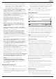
Operation Modes (Fig. A)
WARNING: Do not select the operating mode when the
tool isrunning.
Your tool is equipped with a mode selector dial
4
to selectthe
mode appropriate to desiredoperation.
Symbol Mode Application
Hammering only Lightchipping
Bit Adjustment Chisel bit position adjustment
To Select an Operating Mode
• Rotate the mode selector dial so that the arrow points to the
symbol corresponding for the desiredmode.
NOTE: The arrow on the mode selector dial
4
must be pointing
at a mode symbol at all times. There are no operable positions
inbetween.
Indexing the Chisel Position (Fig.A)
The DCH832 can be indexed and locked into
18differentpositions.
The DCH892 can be indexed and locked into
24differentpositions.
1. Rotate the mode selector switch
4
until it points towards
the position.
2. Rotate the chisel to the desiredposition.
Proper Hand Position (Fig. A, E)
WARNING: To reduce the risk of serious personal injury,
ALWAYS use proper hand position asshown.
WARNING: To reduce the risk of serious personal
injury, ALWAYS hold securely in anticipation of a
suddenreaction.
Proper hand position requires one hand on the bail/loop style
auxiliary handle
2
with the other hand on the mainhandle
5
.
OPERATION
Instructions for Use
WARNING: Always observe the safety instructions and
applicableregulations.
WARNING: To reduce the risk of serious personal
injury, turn tool off and disconnect battery pack
before making any adjustments or removing/
installing attachments or accessories. An accidental
start-up can causeinjury.
2. Pull back the locking sleeve
7
and insert the bitshank.
3. Release the locking sleeve and turn the bit slightly until the
sleeve snaps intoposition.
4. Pull on the bit to check if it is properly locked. The
hammering function requires the bit to be able to move
axially several centimetres when locked in the bitholder.
5. To remove a chisel pull back the bit holder locking sleeve/
collar
7
and pull the chisel out of the chisel holder
6
.
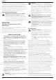
Bail/Loop Style Auxiliary Handle (Fig. C)
WARNING: To reduce the risk of personal injury, ALWAYS
operate the tool with the bail/loop style auxiliary handle
properly installed. Failure to do so may result in the bail/
loop style auxiliary handle slipping during tool operation
and subsequent loss of control. Hold tool with both hands
to maximizecontrol.
The bail/loop style auxiliary handle
2
clamps to the front of
the gear case and may be rotated 360˚ to permit right‑ or
left‑handuse.
Mounting the Bail/Loop Style Auxiliary Handle
(Fig.C)
1. Widen the ring opening
13
of the bail/loop style auxiliary
handle
2
by rotating the screw for handle mounting
14
counterclockwise.
2. Slide the assembly onto the nose of the tool through
the ring opening
13
and onto the chisel position index
collar
3
, past the chisel holder andsleeve.
3. Rotate the bail/loop style auxiliary handle to the
desiredposition.
4. Lock the bail/loop style auxiliary handle in place by securely
tightening the screw for handle mounting
14
rotating it
clockwise so that the assembly will notrotate.
To Remove the Battery Pack from the Tool
1. Press the battery release button
9
and firmly pull the
battery pack out of the toolhandle.
2. Insert battery pack into the charger as described in the
charger section of thismanual.
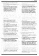
Fuel Gauge Battery Packs (Fig.B)
Some DeWALTDeWALT battery packs include a fuel gauge
which consists of three green LED lights that indicate the level
of charge remaining in the batterypack.
To actuate the fuel gauge, press and hold the fuel gauge
button
16
. A combination of the three green LED lights will
illuminate designating the level of charge left. When the level
of charge in the battery is below the usable limit, the fuel gauge
will not illuminate and the battery will need to berecharged.
NOTE: The fuel gauge is only an indication of the charge left on
the battery pack. It does not indicate tool functionality and is
subject to variation based on product components, temperature
and end‑userapplication.
Bit and Bit Holder
WARNING: Burn Hazard. ALWAYS wear gloves when
changing bits. Accessible metal parts on the tool and bits
may get extremely hot during operation. Small bits of
broken material may damage barehands.
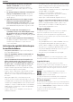
Inserting and Removing SDSmax® Accessories
(Fig.D)
This machine uses SDSmax® chisels (refer to the inset in
FigureD for a cross‑section of an SDSmax® bitshank).
1. Clean the bitshank.
WARNING: Do not apply lubricant to themachine.