
Use and Care Manual


ENGLISH
9
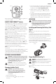
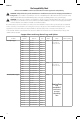
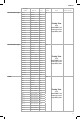
FIG. D
11
14
15
16
17
When the battery state of charge LED
16
is lit, regardless of
color, the tool is ON.
DeWALT
CRIMP CONNECT™ System
This crimping tool is capable of connecting with a computer
via the micro USB port
12
on the back of the tool using the
micro USB cable included with your tool. This allows the
user to connect the
DeWALT
crimping tool to a computer
which utilizes
DeWALT
's CRIMP CONNECT
TM
System software.
NOTE: The CRIMP CONNECT™ System software is governed
by separate terms and conditions available for viewing
through the software download.
Step 1: Download the CRIMP CONNECT™ System software
to your computer at www.dewalt.com/crimpconnect.
Step 2: Follow the instructions in the software to create
your CRIMP CONNECT™ System account.
Step 3: Connect your crimping tool with the
DeWALT
CRIMP CONNECT™ System software by first connecting the
provided micro USB cable to the micro USB port
12
on the
back of the tool to a USB port on a computer. Then go to
the Home screen of the program to access tool tracking and
usage reports stored on the crimping tool.
NOTE: The USB connection will not charge the tool's
batterypack.
For more information on
De
WALT CRIMP CONNECT™ System
functionality and features, please call 1–800–4-
DeWALT
(1–800–433–9258), visit www.
DeWALT
.com or view the FAQ
page and help screens located inside the software.
ASSEMBLY AND ADJUSTMENTS
WARNING: To reduce the risk of serious personal
injury, turn unit off and remove the battery pack
before making any adjustments or removing/
installing attachments or accessories. An
accidental start-up can causeinjury.
WARNING: To reduce the risk of serious personal
injury, do not use the crimping tool with any kind of
die other than those recommended by
DeWALT
.
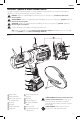
Changing the Dies (Fig. A)
WARNING: Inspect dies and connectors
before use. Only use properly matched dies
and connectors for the crimping head. Refer
to Die Compatibility Chart for die/connector
compatibility.
1. Remove the battery pack.
2. Clean the die holder
1
with a dry clean cloth or
forcedair.
3. Select the appropriate size and type of crimping die for
the connector and cable specified. Refer to engineering
specifications and the Die Compatibility Chart.
4. Slide the dies into each die holder
1
until the ball
detent snaps into the die groove. This locks the die
intoplace.
5. To remove the dies, first remove the battery pack, then
completely open the hydraulic ram by pressing and
holding the reverse trigger switch. Apply force to left or
right side of the die until die slides out of die holder.
OPERATION
WARNING: To reduce the risk of serious personal
injury, turn unit off and remove the battery pack
before making any adjustments or removing/
installing attachments or accessories. An
accidental start-up can causeinjury.
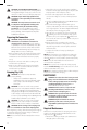
Installing and Removing the Battery Pack
(Fig. E)
NOTE: For best results, make sure your battery pack is
fullycharged.
To install the battery pack into the tool handle, align the
battery pack with the rails inside the tool’s handle and slide
it into the handle until the battery pack is firmly seated in
the tool and ensure that it does notdisengage.
To remove the battery pack from the tool, press the release
button and firmly pull the battery pack out of the tool
handle. Insert it into the charger as described in the charger
section of thismanual.
FIG. E
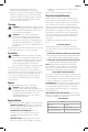
Proper Hand Position (Fig. F)
WARNING: To reduce the risk of serious personal injury,
ALWAYS use proper hand position as shown.
WARNING: To reduce the risk of serious personal injury,
ALWAYS hold securely in anticipation of a sudden
reaction.
Proper hand position requires one hand on the main handle
6
as shown.
FIG. F
6