
Supplementary Document

www.powers.com
6
ADHESIVES
REFERENCE DATA (ASD)
TECH MANUAL – ADHESIVES ©2016 POWERS VOLUME 1 – REV. M
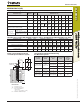
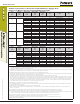
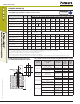
AC100+ Gold Adhesive Anchors Installed
into Grouted Concrete Masonry Wall
AC100+ Gold Adhesive Anchors Installed into
Top of Grouted Concrete Masonry Wall
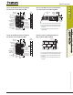
AC100+ Gold adhesive anchors installed into
grouted concrete masonry wall
Wall
Thickness
C2
Min. Edge
Distance
Critical Edge
Distance (see
load tables)
Reduced
Allowable Load
Capacity area
No
Installation
Within 1-1/2"
of Head Joint
(unless joint
mortared full
depth)
Adhesive
Anchor
Full Allowable
Load Capacity Area
Critical End
Distance (see
load tables)
Min. End
Distance
(end of wall)
A
C1
A
A-A
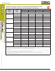
AC100+ Gold Adhesive Anchors Installed into
the Top of Grouted Concrete Masonry Wall
Min. End
Distance
(TYP)
Min. Edge
Distance
(TYP)
Grouted Cell
(TYP)
1
2
3
4
1. Shear load parallel to Edge and perpendicular to End
2. Shear load parallel to End and perpendicular to Edge
3. Shear load parallel to Edge and perpendicular away
from End
4. Shear load parallel to End and perpendicular to
opposite Edge
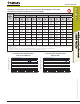
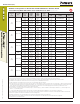
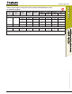
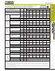
AC100+ Gold Adhesive Anchors Installed
into Hollow Concrete Masonry Wall
Direction of Shear Loading in Relation to
Edge and End of Masonry Wall
AC100+ Gold Adhesive Anchors Installed into
Hollow Concrete Masonry Wall
Wall
Thickness
C2
Min. Edge
Distance
Critical Edge
Distance
Reduced
Allowable
Load
Capacity Area
Full
Allowable Load
Capacity Area
(Hatched Area)
Adhesive
Anchor
Cell Web
(Typ)
Critical End
Distance (see
load tables)
Min. End
Distance
(end of wall)
A
C1
A
A-A
Hollow CMU
(Typ)
Mortal Joint
(Typ)
AC100+ Gold Direction of Shead Loading in
Relation to Edge and End of Masonry Wall
1. Shear load parallel to Edge and perpendicular to End
2. Shear load parallel to End and perpendicular to Edge
3. Shear load parallel to Edge and perpendicular away
from End
4. Shear load parallel to End and perpendicular away
from Edge
Minimum End
Distance (Typ)
Minimum
Edge Distance
(Typ)
Grout Filled
CMU (Typ)
Mortar Joint
1
2
3
4